In the previous tutorial, IoT communication between two devices over Zigbee protocol was demonstrated using two Xbee modules. The two modules were communicating with each other automatically without any human intervention. The two modules were also operating in transparent mode in the previous project.
In this project, an LED light controller is designed where one device controls the LED interfaced at other by communicating data in API mode. In this tutorial, two Xbee module based IoT devices will be designed and configured to communicate with each other over Zigbee protocol. One of these devices in the Zigbee network will be a Coordinator device and the other will be a Router device. The router device will control LED interfaced at the Coordinator device. A switch is interfaced to the Router Xbee. The router Xbee reads the state of this switch every 1 sec and sends the state wirelessly to the Coordinator Xbee. The coordinator Xbee sends the information to its controller via serial communication. The Arduino controls the LED connected to it with that information and notify on serial monitor.
The Zigbee Protocol is one of the most popular standard for Wireless Sensor Networks. The Zigbee is commonly used in industrial IoT applications.
The Xbee devices communicate with each other wirelessly over the air. They do not have any microcontroller or processor in themselves, so they cannot manage the received or sent data. They can simply transfer the information what they receive. But they can be interfaced with other microcontrollers and processors like Arduino, Raspberry Pi or PC via serial Interface.
So, basically, Xbee modules are capable of two types of communication – wireless communication and serial communication. The wireless communication takes place between Xbee devices so that the devices act as radio frequency (RF) devices. For data to transmit and receive from one Xbee module to another, both devices should be on same network. The data between two devices is transmitted wirelessly. By serial communication (UART), the Xbee modules can communicate with microcontrollers and processors.
A microcontroller, processor or PC can send data through the serial interface to the Xbee module (transmitter) and the Xbee module wirelessly transmits the data to other Xbee module (Receiver). The receiver Xbee module transmits the data through the serial interface to controller, processor or PC to which it is interfaced. The controller interfaced to the Xbee module processes the information received by the Xbee devices. This way, controllers can monitor and control remote devices by sending messages through the local Xbee modules.
The Xbee modules communicate with each other in two modes – Transparent mode and API (Application Peripheral Interface) mode. This project is based on Transparent mode. In transparent mode, Xbee modules act as serial line replacement. All data received through serial input is immediately transmitted over the air. When other Xbee module receives data wirelessly, it sends that exactly as it receives through the serial interface and vice versa. Contrary to this, in the API mode, the data is transmitted with some additional information.
In this project, two Xbee modules will be interfaced with Arduino boards. They will be configured to communicate data with each other in API mode. One of the Arduino device will be interfaced with an LED and will be configured as Zigbee Coordinator. The other Arduino device will be configured as Zigbee Router. The Router device will control LED interfaced at the Coordinator device by passing messages over Zigbee protocol in API mode. The Xbee modules interfaced in both devices will be configured as coordinator or router using XCTU software.
This project is a simple demonstration of home Automation services over Zigbee protocol. Like LED, any home appliance can be remotely controlled in similar manner.
The API mode provides a structured interface where packets are transferred in an organized way through serial interface and in a determined order. By default, Xbee devices are configured to work in transparent mode. The transparent mode has some major limitations as following –
1) To read or write the configuration of a device, the device must enter into the command mode.
2) When Xbee receives the data wirelessly, it doesn’t know the source address of the data. If Xbee receives the data from multiple devices then it becomes very hard for the Xbee to distinguish which device has sent the data to the Xbee. For that, in transparent mode, a custom protocol need to be configured on the stack of the Xbee default protocol. All the extra information need to be included in the custom protocol.
3) If a device needs to transmit the different message to different devices, its configuration need to be updated every time, new destination is set.
In order to overcome these problems, there comes API mode. In API mode, there are following provisions to counter above mentioned limitations –
1) There are different frames for different purposes (such as configuration and communication), the read or write devices can be configured without entering in command mode.
2) The API frames includes the source address of the message so the devices can be easily differentiated when multiple devices send data to one device. When the device receives the information, then the source is also notified about the information delivery success.
3) API frame structure includes destination address so different messages can be sent to different devices in API mode.
Component Required –

Fig. 1: List of Components required for LED Light Controller over Zigbee API Mode
Software Required –
• XCTU (6.3.1 or later)
• Arduino IDE
Block Diagram –

Fig. 2: Block Diagram of Xbee API Mode LED Controller
Circuit Connections –
The Xbee Series 2 modules will be used in this project. The X-Bee module is a 20-pin module with the following pin configuration –

Fig. 3: Table listing pin configuration of Xbee Series 2 Module
For connecting the module with PC for configuration, first place the Xbee to the Xbee Shield and connect module with an Arduino. The Arduino UNO or Arduino Mega acts as a USB converter for Xbee modules. Before using Arduino UNO with Xbee modules, a bare minimum sketch must be uploaded on it or the Atmega microcontroller must be removed from the board. The Xbee module can be provided power by an external power supply or from the Arduino. The Xbee module and the Arduino board must communicate serially. The Xbee module should be connected to the Arduino according to the following table –

Fig. 4: Table listing circuit connections between Arduino and Xbee Series 2 Module
Now Arduino can be connected with the PC using a USB cable.
After connecting the module to the computer, perform the following steps –
1) Open the XCTU software. Make sure, the software is in configuration working mode.
2) Click on “Discover Radio Modules”.
3) Click on the desired COM port on which module is connected.
4) Click next, in the ‘Set port parameters’ window, change the values according to the requirements and click finish.
5) As XCTU locates radio modules after full scan, select the radio modules by clicking on ‘Add selected devices’. Now, the selected radio modules should show in radio module window.
In order to transmit or receive data on Xbee modules, they need to be properly configured on the same network. According to the Zigbee protocol one device needs to be in coordinator mode and the rest can be router or end devices. In this case, one device is coordinator and other is router. The Coordinator Xbee is interfaced with LED and is receiving the API frames from Router Xbee. So, the coordinator Xbee will be in API mode. The Router Xbee sends the information exactly received serially from PC so it will be in AT mode.
Now, restore the default setting of all Xbee modules with the ‘Load default firmware setting’ button at the top of Radio configuration section and use XCTU to configure the following parameter –

Fig. 5: Table listing configuration parameters for Xbee Series 2 Module
Fig. 6: Table listing configuration parameters for Xbee Series 2 Module
Keep the rest of the values as default and write the settings of all Xbee modules with the ‘write radio modules’ button at the top of radio configuration. Once the configuration is completed, click on the discover radio modules on same network button of any of the radio module. Now, the radio modules for the same network can be found.
Now the Xbee modules can be connected in the respective circuits.
One of these devices will operate as Zigbee Coordinator. Connect the Xbee module configured as coordinator in its circuit. The Xbee module can communicate with Arduino through serial communication. The Arduino software serial is used to read the data from Xbee and hardware serial to read the controller serial data. As Xbee operates on CMOS logic level and Arduino operates on TTL logic level, there is need of a logic level converter. A 5V to 3.3V IIC I2C Logic Level Interface Level Converter Module for Arduino is used as logic level converter. The Xbee module can be provided power by an external source or from the Arduino. For serial communication between the Arduino board and the Xbee module, RX pin of Xbee is connected to TX of Arduino and TX pin of Xbee is connected to RX of Arduino. The ground pin is connected to the common ground. An LED is interfaced with the Arduino at its PD2 (pin 4) pin through a pull up resistor of 220 ohms.
The other device act as Zigbee Router. Connect the Xbee module configured as router in its circuit. A switch is connected pin 15 of the Router Xbee. The pin 15 by default gets Ground but when the switch is pressed, it receives VCC. It can also be powered with an Arduino board or by an external power supply.
The following precautions must be taken care while interfacing the Xbee modules –
1) Xbee modules operate on 3V3 with current of 40 mA to transmit and receive the data. Don’t provide 5V from Arduino.
2) Xbee modules have 3V3 tolerant signal level. For providing communication between arduino and Xbee, use CMOS-to-TTL logic level converter (Bidirectional).
3) Sometimes when trying to discover Xbee, there may occur an error like – ‘Could not find any device in port COM6 >For input string: “ERROR” or error initializing device parameter = connection timeout or could not find device parameter’ then the error may be because of the incorrect baud rate.
For this, connect the modem using FTDI cable to the PC, open XCTU, select the COM port and multiple baud rates like 9600, 115200, 57600 then search for the radio module and possibly there the radio module can be found. But if not found, then open XCTU legacy (old version), select the possible baud rate and in the modem configuration window select the correct modem firmware/ function set, then enable ‘always update firmware’ and select write. After that, when the info box (action required) appears, then reset the Xbee by connecting RST to GND or simply unseat the Xbee and again place on seat. Now info box will disappear. It will then re-flash the radio modules automatically.
4) If there comes the error of baud rate difference then the error can be that the PC and radio module are not working on same baud rate. In such case, try to change the PC and flash the firmware with another PC. The Xbee module can also be recovered this way.
5) Configure the (Router) module properly when working in API mode.

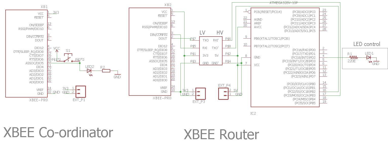
Fig. 7: Image showing circuit connections of Xbee API Mode LED Controller
How the circuit works –
It is important to understand API frame structure for learn how data is communicated in API mode. The structure data packets in API mode are called frames. They are sent and received through the serial interface of the device. They contain the wireless message and some extra information such as source/destination address of the data. Mostly frame length is 22 bytes and contains the following information –

Fig. 8: Table listing API Frame Structure
Start Delimiter – The start delimiter is the first byte of a frame consisting of a specific sequence of the frame indicates the beginning of the data frame. From this, it can be known that the new incoming packet has arrived.
Length – The length field specifies the total number of bytes included in the frame data field.
Frame data – This field contains the message received or transmitted. This includes Frame type, Frame ID, 64 bit source or destination address, 16 bit source or destination address, Send or receive options (Packet acknowledge or not if acknowledge then the value is 01, for broadcast packet, it is 02, for packet encrypted with APS security it is 20 and for packet sent with extended timeout enabled, it is 0x40), Number of sample sets, Digital channel mask, Analog channel mask and RF data (Digital or analog).
Checksum – It specifies the test data integrity.
When the switch connected to router end is pressed or not, the status is notified at the coordinator end and the local LED will also glow when the button will be pressed. The Router receives signal 0 at D3 digital Input pin when switch is not pressed and 1 when switch is pressed. The router sends the signal information to coordinator Xbee wirelessly in a continuous period of 1 sec whether the switch is pressed or not. The coordinator Xbee on receiving the information, by serial communication sends the information to the Arduino serial. The received packet looks like the following –
7E, 0, 12, 92, 0, 13, A2, 0, 41, 26, 85, 81, 25, 4B, 1, 1, 0, 8, 0, 0, 8, check sum.
0, 8 is a digital channel mask which means –

Fig. 9: Bit Values of first and second byte in API Frame
00001000 is 0x8 in hex and 8 in decimal.
The Arduino serial prints the information to the serial monitor whether button is pressed or not. The Arduino does not want to print the whole information. After 19 bytes is the actual message it is receiving, so it will discard the first initial 19 bytes of the frame and start to compare with the message bytes. The following code is used to extract the original message from the received API frame.
if (Button_status == 0)
{
Serial.println(” not pressed”);
digitalWrite(ledPin, LOW);
}
//If receive Button_status as 8, print the status and make the LED high.
else if (Button_status == 8)
{
Serial.println(“pressed”);
digitalWrite(ledPin, HIGH);
}
If the button is pressed then the LED connected to arduino digital pin 2 starts glowing by setting the respective pin HIGH otherwise it will stop glowing by setting the respective pin LOW. In this way, the remote Xbee (Router) is controlling the LED connected to the controller connected to other Xbee (Coordinator). This is a simple demonstration of home automation over Zigbee protocol using Xbee modules in API mode.
In the next tutorial, learn about another IoT protocol – MQTT-SN.
Project Source Code
###


//Program to


/*

  @Aplication: Xbee_digital_button_state


  Breif description:

  This code is for coordinator xbee. When received information from router xbee, the coordinator
xbee transmits the information to Arduino and

  based on that information, arduino controls the led connected to it and print the button status to serial monitor

*/


//Variable to store the status of button

int Button_status = 0;


int ledPin = 2;


void setup()

{

  //Start the serial communication

  Serial.begin(9600);

  pinMode(ledPin, OUTPUT);

}

void loop()

{

  //check whether we are receiving frames or not

  if (Serial.available() > 21)

  {

    //7E indicates the starting of the frame. Now we start receiving the frames.

    //check if the frame received is the starting of the frame

    if (Serial.read() == 0x7E)

    {

      //count the frame bytes up to 19 and discard those bytes.

      for (int i = 0; i < 19; i++)

      {

        byte byte_discarded = Serial.read();

      }

      //After 19 bytes discarded, store the button status signal

      Button_status = Serial.read();

      Serial.print("button is:");


      //If receive button status as 0, print the status and make the lED low

      if (Button_status == 0)

      {

        Serial.println(" not pressed");

        digitalWrite(ledPin, LOW);

      }


      //If receive Button_status as 8, print the status and make the LED high.

      else if (Button_status == 8)

      {

        Serial.println("pressed");

        digitalWrite(ledPin, HIGH);

      }

      Serial.println();

    }

  }

}


###
Circuit Diagrams
Project Video
Filed Under: Arduino., Electronic Projects, Featured Contributions, IoT
Filed Under: Arduino., Electronic Projects, Featured Contributions, IoT

Questions related to this article?
👉Ask and discuss on Electro-Tech-Online.com and EDAboard.com forums.
Tell Us What You Think!!
You must be logged in to post a comment.