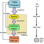
This is the one another Article to introduce the programming of ARM Cortex-M3 LPC1768 Microcontroller. Most tutorials will use pre made libraries in the following tutorials. Sometimes it is needed to make a new library for your own project. This tutorial explains how making a custom library in Keil and this also includes a library built for the GPIO functions of the LPC1768. Setting up the Environment for the development of ARM cortex M3 is well discussed in this article.
The LPC 1768 is ARM Cortex- M3 based Microcontrollers for embedded application features in low power consumption and a high level of integration. The ARM Cortex M3 is designed in a such way to enhance debug features and a higher level of system integration. It clocks at a CPU frequency of 100 MHz, and incorporates a 3-stage pipeline and uses a Harvard architecture with separate local instruction and data buses for third bus peripherals. The ARM Cortex- M3 CPU have an internal pre-fetch unit to support speculative branching. The peripheral components include 512KB of flash memory, 64kb of data memory, Ethernet MAC, USB OTG, 4 UART’s, 8-channel general purpose DMA controller, 2 SSP Controllers, 10-bit DAC, Quadrature encoder interface, SPI interface, 3 I2C bus interface, 2 input plus 2 outputs I2S bus interface, 4 general purpose timers, ultra-low power Real-Time Clock (RTC) with separate battery supply, and up to 70 general purpose I/O pins, 6-output general purpose PWM. The LPC1768/66/65/64 are pin-compatible with the 100-pin LPC236x ARM7-based Microcontroller series.
Libraries:
A library exists of two files, a code file and a header file. They should have the same name, mat_lib for example. The code file is called mat_lib.c and the header file mat_lib.h. The code file is the file containing the actual code that has to be executed and the header files is just a list with all instructions of the library inside. To add new files to a project:

Fig. 1: Add New Files for Project in LPC1768
For this example, we will make the following code in a library:
A = A * 2;
A = A + 2;
The code simply multiplies a variable by 2 and then adds 2. The instruction will be named A = Multiplyadd2(A); For the library 2 files need to be made in the project. A C file and an H file as explained above.
The code for the library has to be placed in a function like this:
void Multiplyadd2( void )
{
//instruction
}
Void means emptiness, if an instruction doesn’t need to send any data back void can be used. The variable we want to modify needs to be sent with the instruction and the instruction has to send a value back. To change the instruction it can use variables from the main code it has to be changed to:
void Multiplyadd2(uint32_t Variable)
Instead of uint32_t any variable can be used. Multiple variables can be used too:
(uint32_t Variable, uint16_t Variable2, Char char3)
The command for the above line is: A = Multiplyadd2(Variable, Variable2, Char3); For the command to multiply and add 2 to a variable it’s just needed to use 1 variable, the one that needs to be multiplied etc.
The instruction also has to send the value back after it is done with the calculations. To do this the void in the beginning has to be changed in a variable:
uint32_t Multiplyadd2(uint32_t Variable)
{
}
Now the actual code can be added to the instruction:
uint32_t Multiplyadd2(uint32_t Variable)
{
Variable = Variable * 2;
Variable = Variable + 2;
return Variable;
}
The return instruction sends the Variable back after the calculations are done. The .c file also needs some includes. In the top of the .c file the following includes needs to be added:
#include “lpc17xx.h”
#include ” types.h”
#include “mat_lib.h”
These includes are needed so the library knows what a microcontroller is used and that variables can be used in the library. It is also possible to add other includes for other libraries so those can be used in the new library.
The only thing that is left is to add the code for the .h file. In the .h files all instructions that can be used are listed. This example library only has one instruction so the code is:
uint32_t Multiplyadd2(uint32_t Variable);
To use the library just include Tutlibrary.h in the main code and it is ready to use. Making libraries for the LPC1768 works the same as making libraries for any C programming language.
Create a project using Keil uvision4 for LPC1768 Microcontroller:
In this section, we will start creating a project in Keil MDK we have already installed Keil µVision and Co-MDK Plug-in + CoLinkEx Drivers required for the CoLinkEx programming adapter. You can start by downloading the project files and experiment the library which is made for GPIO of the LPC1768.
Code Description:
ARM programming requires good handling of Bit manipulation in C language. Here is the small note in the introduction of Bit manipulation to a newbie. C has direct support for bitwise operations that can be used for bit manipulation. In the following examples, n is the index of the bit to be manipulated within the variable bit_fld, which is an unsigned char being used as a bit field. Bit indexing begins at 0, not 1. Bit 0 is the least significant bit.
Set a bit
bit_fld |= (1 << n)
Clear a bit
bit_fld &= ~(1 << n)
Toggle a bit
bit_fld ^= (1 << n)
Test a bit
bit_fld & (1 << n)
The above given GPIO library includes totally 7 functions which can be used to complete the actions of GPIO ease.
· GPIOSetDir( uint32_t portNum, uint32_t bitPosi, uint32_t dir );
· GPIOSetValue( uint32_t portNum, uint32_t bitPosi, uint32_t bitVal );
· GPIOSetPull(uint32_t portNum, uint32_t bitPosi, uint32_t dir);
· GPIOGetValue (uint32_t portNum, uint32_t bitPosi);
· GPIOSetInterrupt ( uint32_t portNum, uint32_t bitPosi, uint32_t dir );
· GPIOClearInterrupt( void );
· uint32_t GPIOCheckInterrupts ( uint32_t portNum, uint32_t dir);
The GPIO ports can be used as input or output, for this tutorial the GPIO port is used as output. The instruction for setting up a GPIO port:
GPIOSetDir(portnum, bitposi, dir);
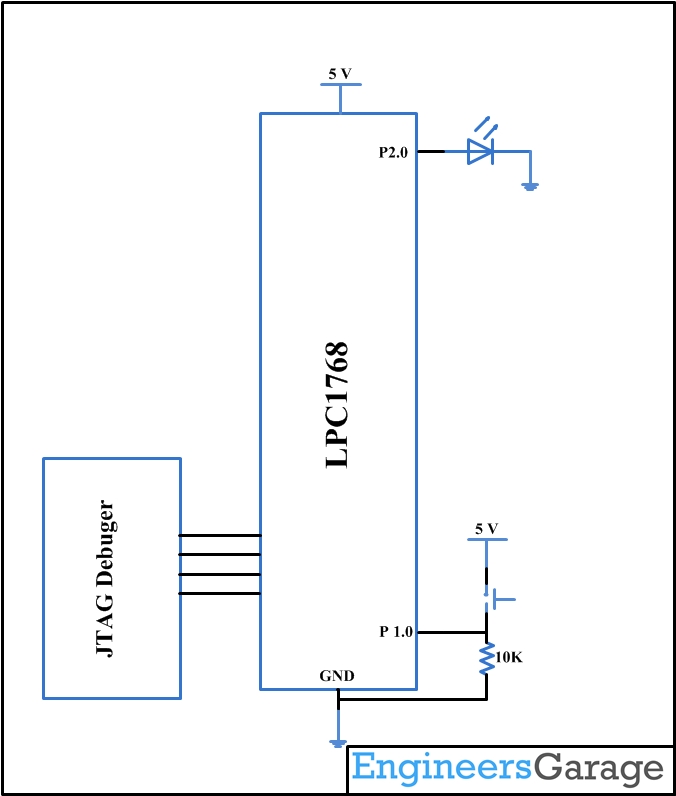
Portnum is the port number, this can be 0 to 4 depending on the IO port that is used. Bitposi is the bit position of the port number; this can be 0 to 31 depending on the IO port that is used. Dir is the direction, 0 for input and 1 for output. It’s also possible to type Input or Output. The IO port that is used for this tutorial is GPIO-1.25 and it is used as an output. The correct instruction for setting up the IO port is:
GPIOSetDir(1, 25, OUTPUT); or:
GPIOSetDir(1, 25, 1);
To turn a IO high or low, the command: GPIOSetValue(portnum, bitposi, value);
Portnum and bitposi are the same as the GPIOSetDir command. Value determents if an IO is on or off, 0 of Low for off and 1 or High for on. To turn the IO pin 1.25 on the command is:
GPIOSetValue(1, 25, HIGH); or
GPIOSetValue(1, 25, 1);
The name of the other functions itself will give the explanations to its use. You can compare these library functions with the Data sheet of LPC1768 for better understanding.
You may also like:


Project Source Code
###The codes are linked in Description ###
Circuit Diagrams
Filed Under: ARM., Tutorials

Questions related to this article?
👉Ask and discuss on Electro-Tech-Online.com and EDAboard.com forums.
Tell Us What You Think!!
You must be logged in to post a comment.