This tutorial series covers embedded system design using MicroPython and the NodeMCU development board. Throughout the series, you’ll learn embedded programming with MicroPython, along with how to interface different I/O devices, sensors, actuators, and other components with the NodeMCU board.
In the previous tutorial, we learned how to interface analog sensors with NodeMCU, including potentiometers, LDRs, and similar devices. These sensors provide a continuously varying output voltage from 0 to 3.3 V, which is why they’re known as analog sensors.
Other sensors have only two output states: high, or 3.3 V, and low, or 0 V. Since their output is either high or low, they’re known as digital sensors. There are many types of digital sensors, and in this tutorial, we’ll learn how to interface a few of the most common and widely used examples.
The IR proximity sensor
An IR proximity sensor is commonly used in object detection applications. It provides a high output when an object is detected in front of the sensor, typically within a range of about 6 to 8 cm.
The sensor works by detecting reflected infrared light. It includes an IR LED, photodiode, comparator, and potentiometer. An output LED is also connected to indicate when an object has been detected.

The circuit works as follows:
- The IR LED emits infrared light. When this light reflects off an object in front of the sensor, typically within about 6 cm, it falls on the photodiode.
- The photodiode conducts, causing the voltage at comparator pin 2 to become lower than the threshold voltage set at pin 3.
- The comparator output becomes high, which is indicated by the output LED.
- When there’s no object in front of the IR LED, the photodiode doesn’t conduct. The voltage at comparator pin 2 remains higher than the voltage at pin 3, so the comparator output remains low.
The circuit operation is simple because the sensor has only two output states: high and low.
When the sensor detects an object in front of it at a distance of about 5 to 6 cm, its output is high. When there’s no object in front of the sensor, its output is low.
This makes the IR proximity sensor easy to interface with NodeMCU or another microcontroller.
The following section shows how to interface an IR proximity sensor with NodeMCU, followed by the circuit operation and MicroPython program.
Circuit diagram
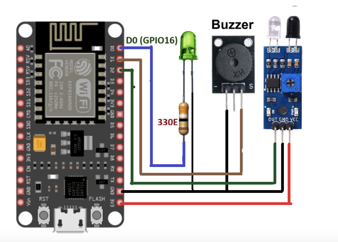
As shown in the figure, the IR proximity sensor is connected to the NodeMCU board along with an LED and buzzer.
The sensor has three interfacing pins: VCC, GND, and OUT. The VCC and GND pins are connected to the 3.3 V and GND pins on the NodeMCU board. The OUT pin provides the sensor output and is connected to digital pin D2.
A green LED is connected to pin D0 through a 330 Ω current-limiting resistor. A 5 V mini buzzer is connected to pin D1.
Circuit operation
When an object comes in front of the sensor, the sensor provides a high signal, or logic 1, to the NodeMCU. When the NodeMCU receives this logic 1 input on pin D2, it blinks the LED and generates a beep sound from the buzzer.
It also prints the message “object detected” on the serial monitor. This means the NodeMCU provides both audio and visual notification when an object is detected by the sensor.
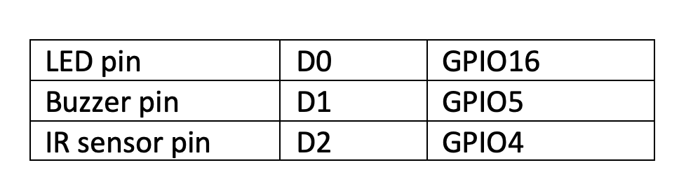
Pin mapping
Micropython program for interfacing the IR proximity sensor
from machine import Pin
from machine import time
led = Pin(16, Pin.OUT)
buz = Pin(5, Pin.OUT)
ir_sensor_pin = Pin(4, Pin.IN)
led.off()
buz.off()
while True:
if ir_sensor_pin().value == 1:
print(‘object detected’)
led.on()
buz.on()
sleep(0.3)
led.off()
buz.off()
The Line Follower Robot (LFR) sensor
As the name suggests, this sensor is commonly used in line follower robots. It’s also an IR-based proximity sensor, so its components, circuit connections, and working principle are similar to the IR proximity sensor discussed earlier.
In this application, the sensor is used to detect a black line on a white background, or in some cases, a white line on a black background.
When infrared light falls on a white surface, it’s reflected back toward the sensor. The reflected light is detected by the photodiode, and the sensor provides a high output, or logic 1. When infrared light falls on a black surface, it’s absorbed instead of reflected, so the sensor provides a low output, or logic 0.
This allows the same IR sensor to detect a white surface as logic 1 and a black surface as logic 0.
Now, let’s look at how to interface an LFR sensor with NodeMCU. The circuit diagram is followed by the circuit operation and MicroPython program.
Circuit diagram
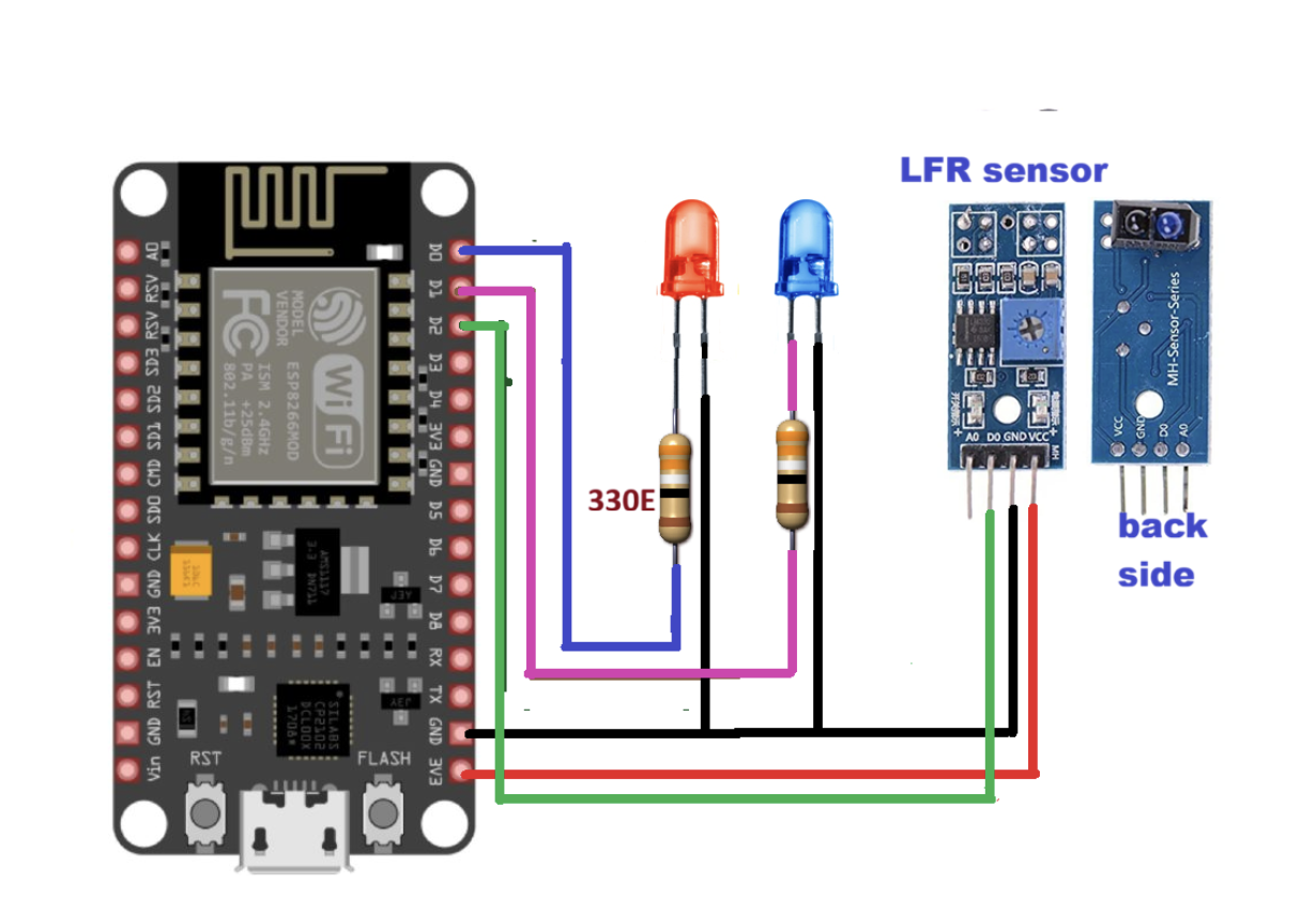
In the above diagram, the LFR sensor is connected to the NodeMCU board along with two LEDs: one red and one blue. The sensor connections are similar to the previous IR proximity sensor circuit.
The sensor has four interfacing pins: VCC, GND, D0, and A0. The VCC and GND pins are connected to the 3.3 V and GND pins on the NodeMCU board. The D0 pin provides the digital output from the sensor and is connected to digital pin D2. The A0 pin provides the analog output, but it’s not used in this tutorial.
A red LED is connected to pin D0 through a 330 Ω current-limiting resistor, and a blue LED is connected to pin D1.
Circuit operation
As shown in the figure, the IR LED and photodiode module are located on the underside of the sensor. The sensor is placed about 4 to 5 cm above the black and white surface.
When the sensor is above a black surface, it provides a logic 0 output. The NodeMCU reads this logic 0 input on pin D2, turns on the red LED, and displays the message “black line” on the serial monitor.
When the sensor is above a white surface, it provides a logic 1 output. The NodeMCU reads this logic 1 input on pin D2, turns on the blue LED, and displays the message “white line” on the serial monitor.
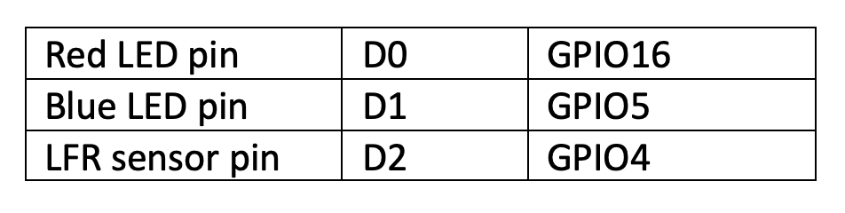
Pin mapping
Micropython program for interfacing the LFR sensor
from machine import Pin
from machine import time
red_led = Pin(16, Pin.OUT)
blue_led = Pin(5, Pin.OUT)
lfr_sensor_pin = Pin(4, Pin.IN)
red_led.off()
blue_led.off()
while True:
if lfr_sensor_pin().value == 0:
print(‘black line’)
red_led.on()
blue_led.off()
else:
print(‘white line’)
red_led.off()
blue_led.on()
sleep(0.2)
The flame sensor
This sensor is used to detect fire or flame. It works by detecting infrared radiation emitted by fire, flame, or another hot object.
The sensor includes an IR photodiode, comparator, and potentiometer. The IR photodiode senses infrared radiation, while the potentiometer is used to set the detection threshold.
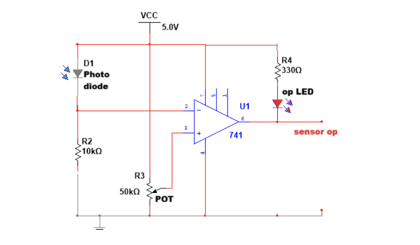
The IR photodiode detects infrared radiation from a hot body. This value is then compared with the threshold value set using the potentiometer. Once the detected radiation reaches the threshold value, the comparator output goes low. This means the sensor provides a low output when it detects a flame.
The following circuit diagram shows how to interface the flame sensor with NodeMCU.
Circuit diagram
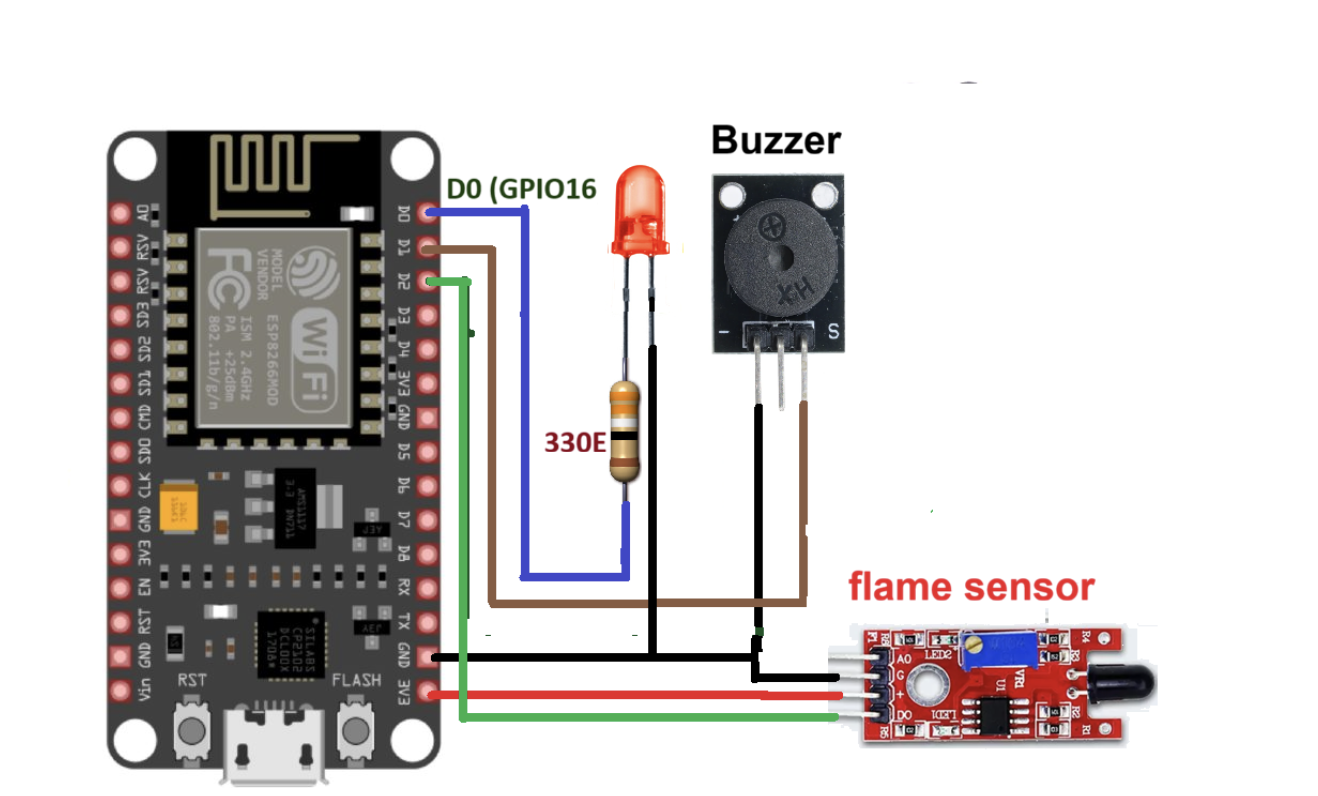
As shown in the figure, the flame sensor is connected to the NodeMCU board along with an LED and buzzer. The connections are similar to the previous circuit used to interface the IR proximity sensor.
The sensor has four interfacing pins: VCC, GND, D0, and A0. The VCC and GND pins are connected to the 3.3 V and GND pins on the NodeMCU board. The D0 pin provides the digital output from the sensor and is connected to digital pin D2. The A0 pin provides the analog output, but it’s not used in this tutorial.
A red LED is connected to pin D0 through a 330 Ω current-limiting resistor. A 5 V mini buzzer is connected to pin D1.
Circuit operation
When the sensor detects fire or flame, it provides a low signal, or logic 0, to the NodeMCU. When the NodeMCU receives this logic 0 input on pin D2, it blinks the LED and generates a beep sound from the buzzer.
It also prints the message “flame detected” on the serial monitor. This means the NodeMCU provides both audio and visual notification when a flame is detected by the sensor.
Pin mapping
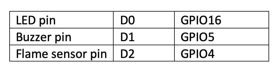
Micropython program for interfacing the flame sensor
from machine import Pin
from machine import time
led = Pin(16, Pin.OUT)
buz = Pin(5, Pin.OUT)
flame_sensor_pin = Pin(4, Pin.IN)
led.off()
buz.off()
while True:
if flame_sensor_pin().value == 0:
print(‘flame detected’)
led.on()
buz.on()
sleep(0.3)
led.off()
buz.off()
Note, there are several more digital sensors (such as the opto-interrupt sensor, vibration sensor, tilt sensor, etc.), which provide high or low outputs. All of these sensors can easily be interfaced with a. NODEMCU board.
In next tutorial, we’ll discuss how to interface advanced or smart sensors (such as the DHT and UDM sensor) with NODEMCU.
You may also like:
Filed Under: Tutorials
Log in to leave a comment:
Lost your password?
Don't have an account? Register here