Engineers Garage

  • Projects and Tutorials
    • Electronic Projects
      • 8051
      • Arduino
      • ARM
      • AVR
      • PIC
      • Raspberry pi
      • STM32
    • Tutorials
    • Circuit Design
    • Project Videos
    • Components
  • Articles
    • Tech Articles
    • Insight
    • Invention Stories
    • How to
    • What Is
  • News
    • Electronic Products News
    • DIY Reviews
    • Guest Post
  • Forums
    • EDABoard.com
    • Electro-Tech-Online
    • EG Forum Archive
  • Digi-Key Store
    • Cables, Wires
    • Connectors, Interconnect
    • Discrete
    • Electromechanical
    • Embedded Computers
    • Enclosures, Hardware, Office
    • Integrated Circuits (ICs)
    • Isolators
    • LED/Optoelectronics
    • Passive
    • Power, Circuit Protection
    • Programmers
    • RF, Wireless
    • Semiconductors
    • Sensors, Transducers
    • Test Products
    • Tools
  • EE Resources
    • DesignFast
    • LEAP Awards
    • Oscilloscope Product Finder
    • White Papers
    • Webinars
  • EE Learning Center
  • Women in Engineering

Digital clock using DS12C887 and 8051 microcontroller (AT89C51) in 12 hour mode

By Himanshu Choudhary

This article is an improved version of LCD based clock using RTC DS12C887 and 8051 microcontroller (AT89C51) using update interrupt. DS12C887 has two modes of operation i.e., 12 hour and 24 hour mode. In our earlier articles we explained how to use 24 hour mode. This article explores how we can use the 12 hour mode of RTC. This is done by making a clock using RTC and 8051 microcontroller (AT89C51) with 12 hour mode operation. The clock time is displayed on a 16x2 LCD interface. The free source code for the program is available in C.


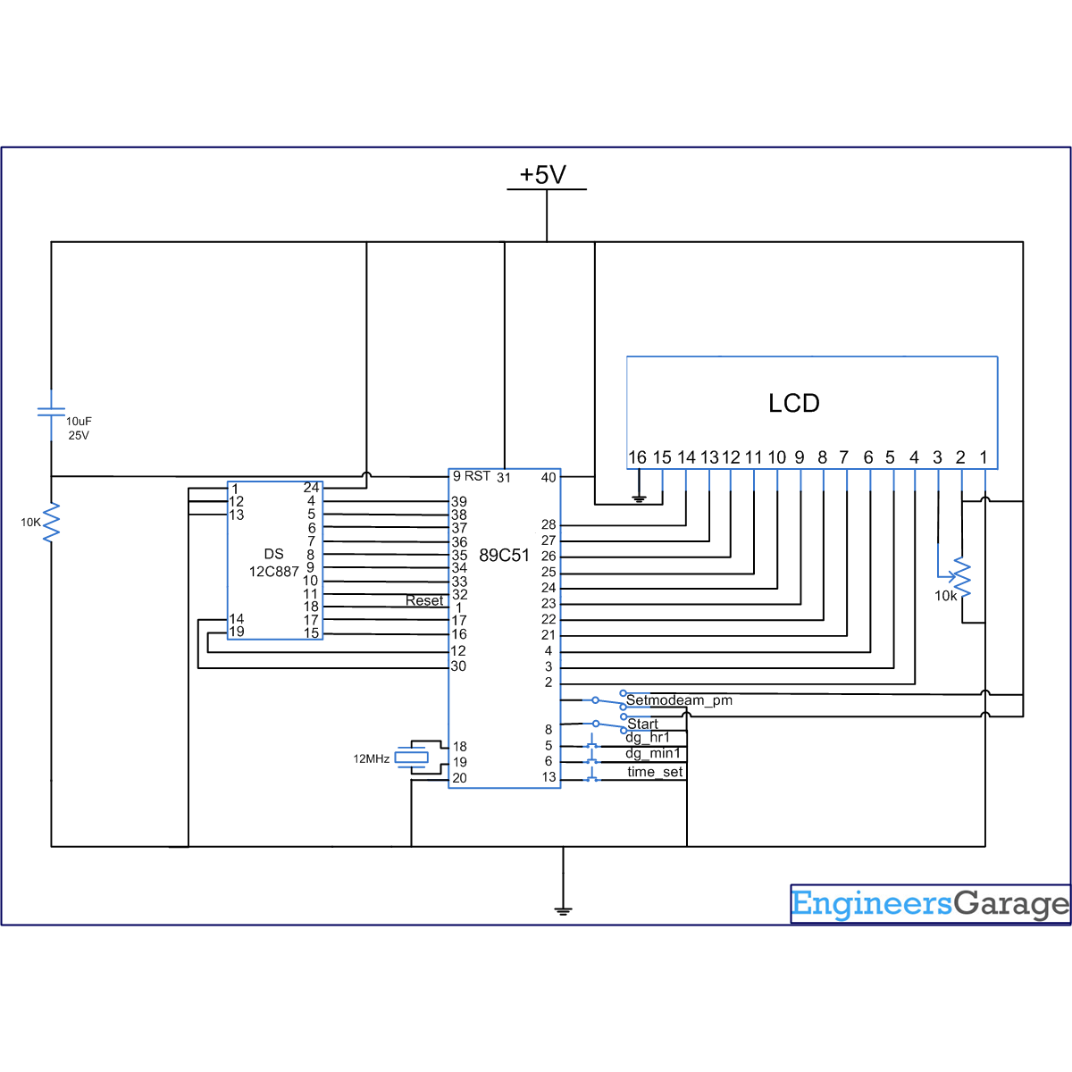
The circuit diagram shows the connection of RTC with the microcontroller. Port P2 is used as data port for LCD while port P0 of the microcontroller AT89C51 is used as data port for the RTC DS12C887. The pins P1^0 – P1^7 of the microcontroller are configured as reset, rs, rw, e, dig_hr1, dig_min1, start, setmode, am_pm pins respectively.

Clock principally works on two modes. In the 24 hour mode hours are counted from 0 to 23 and in the 12 hour mode hours are counted from 0 to 11. In the 12 hour mode the RTC returns the BCD value 1-12 for AM and 81-92 for PM. The RTC returns the BCD value 1 for 1 AM.
The values corresponding to the output 1 to 12 i.e., 0 to 11 are stored in an array nummin. An array numhr is used to store the values from 81 to 92. When RTC sends the output, microcontroller reads hours and if it matches with any of the numhr variable it displays corresponding value from nummin array else it displays the same value for hours. This trick is used to convert the RTC from 24 hour mode to 12 hour mode.
Interrupt 0 of controller is used to get time by update interrupt. Interrupt 2 is used for setting the time. 24 hour mode can be used as explained in LCD based clock using RTC DS12C887 and 8051 microcontroller (AT89C51) using update interrupt.


Project Source Code

###


//Program for Digital clock using DS12C887 & 8051 microcontroller (AT89C51) in 12 hour mode
/*12hr clock
set p3^3=0,then start=0 them set time by dig_hr1 & dig_min1, then remove p3^3 & start
am:p1^7=0	 pm:p1^7=1*/

#include<reg51.h>
#include<absacc.h>
#define dataport P2
#define port P1

sbit reset = port^0;
sbit rs = port^1;
sbit rw = port^2;
sbit e =port^3;
sbit dig_hr1=port^4;
sbit dig_min1=port^5;
sbit start=port^6;
sbit setmodeam_pm=port^7;

int hr1=0;
int min1=0;
int modeam_pm=0,q,am_pm;
unsigned char numhr[12]={0x81,0X82,0X83,0X84,0X85,0X86,0X87,0X88,0X89,0X90,0X91,0X92};
unsigned char temp,hr,min,sec,nummin[60]={0X00,0X01,0X02,0X03,0X04,0X05,0X06,0X07,0X08,0X09,0X10,0X11,0X12,0X13,0X14,0X15,0X16,0X17,0X18,0X19,0X20,0X21,0X22,0X23,0X24,0X25,0X26,0X27,0X28,0X29,0X30,0X31,0X32,0X33,0X34,0X35,0X36,0X37,0X38,0X39,0X40,0X41,0X42,0X43,0X44,0X45,0X46,0X47,0X48,0X49,0X50,0X51,0X52,0X53,0X54,0X55,0X56,0X57,0X58,0X59};

 void delay(unsigned int msec )
{
	int i ,j ;
	for(i=0;i<msec;i++)
	for(j=0; j<1275; j++);
}

void lcd_cmd(unsigned char item)
{
	dataport = item;
	rs= 0;
	rw=0;
	e=1;
	delay(1);
	e=0;
	return;
}
 
// DATA SENDING FUNCTION
void lcd_data(unsigned char item)
{
	dataport = item;
	rs= 1;
	rw=0;
	e=1;
	delay(1);
	e=0;
	return;
}

void lcd_data_string(unsigned char *str)
{
	int i=0;
	while(str[i]!='')
	{
		lcd_data(str[i]);
		i++;
		delay(1);
	}
	return; 
}

lcd_data_int(int time_val)
{
	int int_amt;
	int_amt=time_val/10;
	lcd_data(int_amt+48);
	int_amt=time_val%10;	 
	lcd_data(int_amt+48);
}

void lcd()			// Function to intitialize LCD
{
	lcd_cmd(0x38);		  
	delay(5);
	lcd_cmd(0x0F);        
	delay(5);
	lcd_cmd(0x80);
	delay(5);
}

void set_rtc_time()  
{
	if(modeam_pm==2)
	{
		hr=numhr[hr1];
	}
	XBYTE[10]=0x20;
	XBYTE[11]=0x80;
	XBYTE[0]=0x00;
	XBYTE[2]=min;
	XBYTE[4]=hr;
	XBYTE[7]=0x01;
	XBYTE[8]=0x01;
	XBYTE[9]=0x10;
	XBYTE[1]=0xFF;
	XBYTE[3]=0xFF;
	XBYTE[5]=0xFF;
	XBYTE[11]=0x20;
}

void set_hr1()
{
	hr1++;
	if(hr1>11)
	hr1=0;
	lcd_cmd(0xc3);
	lcd_data_int(hr1);
	lcd_data(':');
}

void set_min1()
{
	min1++;
	if(min1>59)
	min1=0;
	lcd_cmd(0xc6);
	lcd_data_int(min1);
}


void set_time()	interrupt 2	   //Time set function
{
	lcd_cmd(0x01);
	if(start==0)
	{
		lcd_data_string("SET TIMING");
		lcd_cmd(0xc3);
		lcd_data_int(hr1);
		lcd_data(':');
		lcd_data_int(min1);
		while(start==0)
		{
			delay(10);
			if(dig_hr1==0)
			set_hr1();
			if(dig_min1==0)
			set_min1();
			if(setmodeam_pm==0)	 
			{
				modeam_pm=1;
			}
			else
			{
				modeam_pm=2;
			}
		}
	}
	lcd_cmd(0x01);
	hr=nummin[hr1];
	min=nummin[min1];
	set_rtc_time();
}

bcdconv(unsigned char mybyte)
{
	unsigned char x,y;
	x=	mybyte & 0x0F;
	x=x | 0x30;
	y= mybyte & 0xF0;
	y=y>>4;
	y=y | 0x30;
	lcd_data(y);
	lcd_data(x);
}

void read_rtc_display() interrupt 0			//Alarm interrupt
{ 
	lcd_cmd(0x01);
	lcd_cmd(0x80);
	lcd_data_string("TIME:");
	lcd_cmd(0X86);
	reset=0;
	reset=1;
	XBYTE[11]=0x10;
	hr=XBYTE[4];
	temp=0x87;
	for(q=0;q<12;q++)
	if(hr==numhr[q])
	{
		hr=nummin[q+1];
		am_pm=2;
		if(q==11)
		hr=0x00;
	}
	else
	am_pm=1;
	bcdconv(hr);
	lcd_data(':');
	min=XBYTE[2];
	bcdconv(min);
	lcd_data(':');
	sec=XBYTE[0];
	bcdconv(sec);
	if(am_pm==1)
	{
		lcd_data_string("am");
	}
	else
	{
		lcd_data_string("pm");
	}
}

void main()
{
	setmodeam_pm=0;
	setmodeam_pm=1;
	reset=1;
	lcd();
	XBYTE[10]=0x20;
	XBYTE[11]=0x10;
	lcd_cmd(0x01);
	IE=0x85;
	while(1);
}

###


Circuit Diagrams

Circuit-Diagram-Digital-Clock-Using-DS12C887-8051-Microcontroller-AT89C51-12-Hour-Mode

Project Components

  • AT89C51 Microcontroller
  • LCD
  • RTC DS12C887

Project Video


Filed Under: 8051 Microcontroller
Tagged With: 8051, clock, ds12c887, microcontroller
 

Questions related to this article?
👉Ask and discuss on EDAboard.com and Electro-Tech-Online.com forums.


Tell Us What You Think!! Cancel reply

You must be logged in to post a comment.

HAVE A QUESTION?

Have a technical question about an article or other engineering questions? Check out our engineering forums EDABoard.com and Electro-Tech-Online.com where you can get those questions asked and answered by your peers!


Featured Tutorials

  • Designing Gate Driver Circuit and Switching Mechanism for Modified Sine Wave Inverter – (Part 9/17)
  • Completing Modified Sine Wave Inverter Design with Full Bridge Circuit and Step Up Transformer – (Part 10/17)
  • Designing an Offline UPS – Part (12 /17)
  • How to reduce Switching Time of a Relay – (Part 15/17)
  • Testing MOSFET – (Part 16/17)
  • Driving High Side MOSFET using Bootstrap Circuitry – (Part 17/17)

Stay Up To Date

Newsletter Signup

Sign up and receive our weekly newsletter for latest Tech articles, Electronics Projects, Tutorial series and other insightful tech content.

EE Training Center Classrooms

EE Classrooms

Recent Articles

  • MicroPython – I2C protocol in ESP8266 and ESP3
  • New automotive radar sensor enables reliable in-cabin monitoring system
  • TI breaks ground on 300-mm semiconductor wafer-fabrication plants in Texas
  • New wireless AR Smart Viewer reference design
  • Infineon launches scalable and wireless charging platform with configurable controllers

Most Popular

5G 555 timer circuit 8051 ai Arduino atmega16 automotive avr dc motor display Electronic Part Electronic Parts Fujitsu ic infineontechnologies integratedcircuit Intel IoT ir lcd ldr led maximintegratedproducts microchip microchiptechnology Microchip Technology microcontroller microcontrollers mosfet motor powermanagement Raspberry Pi remote renesaselectronics renesaselectronicscorporation Research samsung semiconductor sensor software STMicroelectronics switch Technology vishayintertechnology wireless

RSS EDABOARD.com Discussions

  • Photovoltaic MOSFET Drivers - Voltage Rating
  • Impedance requirement for SDRAM signals
  • A circuit that can adjust a resistance and probing a voltage node
  • A analogue circuit that spit out the resistance desired
  • DC to DC buck converter

RSS Electro-Tech-Online.com Discussions

  • Finally switched to Linux.
  • How to quickly estimate lead acid battery capacity ?
  • Multistage BJT amplifier
  • VOLTAGE GAIN AND VOUT RESISTENCE OF TRANSISTOR IN AC CIRCUIT
  • Enclosure sought
Engineers Garage
  • Analog IC TIps
  • Connector Tips
  • DesignFast
  • EDABoard Forums
  • EE World Online
  • Electro-Tech-Online Forums
  • Microcontroller Tips
  • Power Electronic Tips
  • Sensor Tips
  • Test and Measurement Tips
  • 5G Technology World
  • About Us
  • Contact Us
  • Advertise

Copyright © 2022 WTWH Media LLC. All Rights Reserved. The material on this site may not be reproduced, distributed, transmitted, cached or otherwise used, except with the prior written permission of WTWH Media
Privacy Policy | Advertising | About Us

Search Engineers Garage

  • Projects and Tutorials
    • Electronic Projects
      • 8051
      • Arduino
      • ARM
      • AVR
      • PIC
      • Raspberry pi
      • STM32
    • Tutorials
    • Circuit Design
    • Project Videos
    • Components
  • Articles
    • Tech Articles
    • Insight
    • Invention Stories
    • How to
    • What Is
  • News
    • Electronic Products News
    • DIY Reviews
    • Guest Post
  • Forums
    • EDABoard.com
    • Electro-Tech-Online
    • EG Forum Archive
  • Digi-Key Store
    • Cables, Wires
    • Connectors, Interconnect
    • Discrete
    • Electromechanical
    • Embedded Computers
    • Enclosures, Hardware, Office
    • Integrated Circuits (ICs)
    • Isolators
    • LED/Optoelectronics
    • Passive
    • Power, Circuit Protection
    • Programmers
    • RF, Wireless
    • Semiconductors
    • Sensors, Transducers
    • Test Products
    • Tools
  • EE Resources
    • DesignFast
    • LEAP Awards
    • Oscilloscope Product Finder
    • White Papers
    • Webinars
  • EE Learning Center
  • Women in Engineering