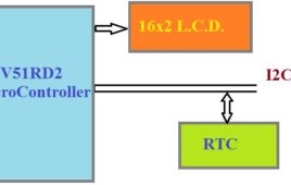
A real-time clock (RTC) is a computer clock to keep time and is one of the more popular microcontroller features. Microcontrollers without a built-in RTC require an external RTC chip for keeping time. Typically, mid-segment to high-end microcontrollers have a built-in RTC because time-keeping is necessary for several embedded applications. RTCs count seconds, minutes, hours,…
Renesas releases new programmable clock generator
Renesas Electronics Corporation, a supplier of advanced semiconductor solutions, has introduced the VersaClock 7 clock generators, a family of configurable clock generators with an internal crystal oscillator for PCIe and networking applications in high-end computing, wired infrastructure, and data center equipment. The VersaClock 7 delivers unmatched flexibility, enabling designers to configure frequencies, Input/Output (I/O) levels,…
Renesas offers industry’s first PCIe Gen6 clock buffers and multiplexers
Renesas Electronics Corporation, a supplier of advanced semiconductor solutions, has introduced the first clock buffers and multiplexers that meet stringent PCIe Gen6 specifications. The company is offering 11 new clock buffers and four new multiplexers. These new devices, which also support and provide extra margin for PCIe Gen5 implementations, complement Renesas’ low-jitter 9SQ440, 9FGV1002 and…
Renesas expands its ProXO oscillator portfolio for high-performance communication
Renesas Electronics Corporation, a supplier of advanced semiconductor solutions, is expanding its timing solutions portfolio with the ProXO+ family of compact, ultra-low noise, temperature-controlled clock oscillators. The high-accuracy, high-frequency, differential oscillators are best suited for fiber optic transceiver modules, accelerator cards, smart NIC cards, and networking equipment applications. “The ProXO+ family delivers on all counts, offering…
Clock with LED pendulum with tick tock sound
Many of us see different kinds of wall clock available in market which produces sound but they are very expensive. The circuit described here produces a tick tock sound and also indicate the time with the help of LED. In this circuit, LED’s are arranged such that you will get time in the form of a pendulum first in one direction than in opposite direction. So you can make your own watch in much less price as compared to market.This simple circuit is based on two IC’s namely NE555 timer and CD4017 with few more discrete components. 555 timer IC wired as an a-stable oscillator. In this circuit NE555 a-stable generates a clock for the Circuit, which provide a oscillating wave to the output pin 3 of IC1. You can vary the speed of oscillation with the help of R2.
Real Time Clock using 8051 Microcontroller and RTC IC DS1307
A Real Time Clock (RTC) is basically just like a watch – it runs on a battery and keeps time for you even when there is a power outage. Using an RTC, you can keep track of long timelines, even if you reprogram your microcontroller or a power plug.The real time clock (RTC) is widely used device that provides accurate time and date for many applications. Many systems such as IBM pc come with RTC chip on mother board.RTC chip uses an internal battery which keeps time and date even when the power is off. In some microcontrollers have inbuilt RTC while others requires interfacing.Most widely used RTC chip is DS1307 from Dallas Semiconductor. It uses external lithium battery of 3V to keep operating for over maximum 10 years in the absence of external power supply.DS1307 uses CMOS technology to keep power consumption low. According to datasheet of DS1307 from Dallas, it keeps track of “Seconds, Minutes, and Hours, Day of week, Date, Month and Year”.
Interfacing ADC0808 with Serial port (RS232) using interrupt clock from 8051 microcontroller (AT89C51)- (Part 27/45)
In many applications data collected from multiple sensors is transmitted to PC for display or further analysis. The conversion of data from analog to digital form is done using an ADC. The digital data from the ADC is transferred to the computer using serial port. This circuit demonstrates the principle and operation of interfacing an ADC0808 with serial port of PC using the microcontroller AT89C51. The circuit is divided into three parts: ADC, controller and serial port. This circuit can be used as an intermediate circuit in many applications.ADC0808 which is an 8-bit resolution ADC has eight input channels i.e., it can take a maximum of eight analog inputs. The circuit uses the first analog input pin to take the analog input signals from the preset. To provide clock input to the ADC, Timer0 is used in interrupt enabled mode to generate a clock of frequency 500 KHz. To enable the Timer0 in interrupt enable mode, the register IE is loaded with the value 0x82. Every time the timer completes the counting, pin P1.2 toggles its state.
Digital Clock without Microcontroller
Digital clocks normally function by microcontrollers. Here is a circuit for electronic enthusiasts who can make a digital clock without using any expensive controllers, or having no knowledge of microcontrollers or programming. The whole functioning is solely based on simple IC’s. Components used IC 555 (Timer) — one. CD4518 (CMOS dual up counter) — two.…
Field Programmable Gate Array (FPGA) : An Overview
Simulations and prototyping have been a very important part of the electronics industry since a very long time now. Before heading in for the actual fabrication of a dedicated hardware, everyone would want to be sure that what they are making will work the way they want it to. Over all these years while electronics companies offered dedicated hardware in their products, it was not possible for the end user to reconfigure them to his own needs. This need led to the growth of a new market segment of customer configurable Field Programmable integrated circuits called Field Programmable Gate Arrays or FPGA.
Digital clock using DS12C887 and 8051 microcontroller (AT89C51) in 12 hour mode
This article is an improved version of LCD based clock using RTC DS12C887 and 8051 microcontroller (AT89C51) using update interrupt. DS12C887 has two modes of operation i.e., 12 hour and 24 hour mode. In our earlier articles we explained how to use 24 hour mode. This article explores how we can use the 12 hour mode of RTC. This is done by making a clock using RTC and 8051 microcontroller (AT89C51) with 12 hour mode operation. The clock time is displayed on a 16×2 LCD interface. The free source code for the program is available in C.Port P2 is used as data port for LCD while port P0 of the microcontroller AT89C51 is used as data port for the RTC DS12C887. The pins P1^0 – P1^7 of the microcontroller are configured as reset, rs, rw, e, dig_hr1, dig_min1, start, setmode, am_pm pins respectively.
Clock using RTC DS12C887 & 8051 microcontroller (AT89C51) with alarm set function
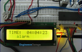
DS12C887 is a real time clock (RTC) IC from Dallas Semiconductors. The RTCs provide precise time and date information. This article explains the making of a [[wysiwyg_imageupload::]]digital clock with alarm setting functionalities. RTC has been interfaced with AT89C51 to perform desired operations. This project is an improvement over Digital clock using RTC DS12C887 and 8051 microcontroller (AT89C51) with time set and has the alarm setting function also. The alarm setting function allows user to set the alarm. The clock time is displayed on the LCD. The free source code for the program is available in C.The circuit for interfacing the RTC and 16×2 LCD with the microcontroller 8051 is shown in the circuit diagram. Port P2 is set as data port for LCD to send the data on the LCD while port P0 is set as data port for the RTC DS12C887.
Digital clock using RTC DS12C887 and 8051 microcontroller (AT89C51) using update interrupt
This article is an improved variant of Digital clock using RTC DS12C887 and 8051 with time set. In the earlier article, we discussed the basics of extracting data from [[wysiwyg_imageupload::]]the RTC DS12C887 using the 8051 microcontroller (AT89C51). This article is in continuation to the above article and introduces you to the concept of handling interrupts for extracting time and other information from the RTC.Interrupts offer a great flexibility to handle RTC. Interrupts have several advantages over the method of polling as discussed in the previous article. It reduces the unnecessary usage of microcontroller’s memory and processing powers, thereby keeping the processor free for other use. RTC 12C887 has three interrupts, namely, Alarm interrupt, Periodic interrupt & Update ended interrupt. For detailed information, check RTC interrupts. The free source code for the program is available in C.This article assumes that the user is aware of real time clock and the basic interfacing of DS12C887 with 8051 microcontroller (AT89C51) including the pin description, memory and registers of RTC DS 12C887.
Digital clock using RTC DS12C887 and 8051 microcontroller (AT89C51) with time set
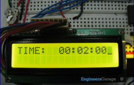
Real time clock (RTC) is widely used in many application to provide accurate time. This article explains the making of a simple digital clock using RTC DS 12C887 and 8051 microcontroller (AT89C51). The output is displayed on an LCD. This clock also has a provision of setting time at any instant. The clock uses the concept of our earlier articles of interfacing RTC DS12C887 with microcontroller. The clock described here uses the method of polling for running. For further details on interfacing RTC DS12C887 with AT89C51 using polling, refer RTC interfacing. The free source code for the program is available in C. The circuit diagram shows the connection of RTC with the microcontroller. Port P2 is used as data port for LCD; port P0 of the microcontroller is used as data port of RTCDS12C887. The pins P1^0, P1^1, P1^2, P1^3, P1^4, P1^5, P1^6 of controller AT89C51 are configured as reset, rs, rw, e, dig_hr1, dig_min1, start pins respectively.
How to interface LDR with ADC0808 using interrupt clock from 8051 microcontroller (AT89C51)- (Part 26/45)
This circuit demonstrates the principle and operation of interfacing an LDR with ADC0808 using the controller AT89C51. This is an 8 channel ADC i.e., it can take [[wysiwyg_imageupload::]]eight input signals. The output is displayed on the LCD. ADC0808 is an 8-bit resolution IC with eight input pins. LDR is used to provide the analog input. The output of the LDR is displayed on a 16×2 LCD. A clock of frequency 500 KHz is generated using Timer0 in the interrupt mode. To enable the interrupt, the value of the register IE is set to 0x82.The output pins of ADC are connected to the port P0 of the AT89C51. The pin10 of the ADC is connected to pin8 (P1.7) of the controller for clock input. ALE, pin22 of the ADC is connected to pin1 (P1.0) of controller. OE, pin9 of the ADC is connected to pin4 (P1.3) of controller. SC, pin6 of the ADC is connected to pin2 (P1.1) of the controller. EOC, pin number 7 is connected to pin 3 (P1.2) of controller.
Digital alarm clock with thermometer using 8051 microcontroller (AT89C51)
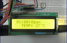
Celsius scale thermometer displays the ambient temperature through a LCD display. It consists of two sections. One is that which senses the temperature. This is a temperature sensor LM 35. The other section converts the temperature value into a suitable number in Celsius scale which is done by the ADC0804. A digital thermometer can be easily made by interfacing…
How to interface ADC0808 with 8051 microcontroller (AT89C51) using clock from D-flip flop- (Part 28/45)
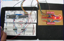
An analog-to-digital converter is a device which converts continuous signals to discrete digital numbers. Typically, an ADC is an electronic device that converts [[wysiwyg_imageupload::]]an input analog voltage (or current) to a digital number proportional to the magnitude of the voltage or current. This circuit demonstrates the interfacing of ADC0808 with 8051 microcontroller (AT89C51). The output is taken on the LEDs. This is an intermediate circuit, which finds lot of applications. ADC0808 needs an external clock to run. The circuit describes how a D-flip flop can be used to provide the external clock. Analog-to-digital converters are among the most widely used devices for data acquisition. Digital computers use binary values, but in physical world everything is analog. Therefore, we need an analog-to-digital converter to translate the analog signals to digital signals. An ADC has n-bit resolution where n can be 8,10,12,16 etc. The ADC chips are either parallel or serial. In parallel ADC we have 8 or more pins dedicated to bringing out the binary data. ADC0808 is a parallel ADC with 8-bit resolution.
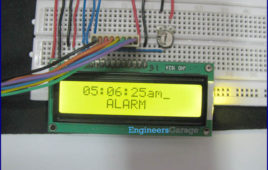
Digital alarm clock using LCD and 8051 microcontroller
An alarm clock is a clock that indicates a pre-set time by producing sound at that time. This functionality of digital clock is used to awaken people or remind them [[wysiwyg_imageupload::]]of something. This circuit is an extension to the digital clock with time setting option. Here an extra switch is provided to set the alarm. While the alarm is set, the clock time does not stop and runs in the background.The circuit is build around 8051 microcontroller (AT89C51) and uses LCD to display time. This is an improved version of digital clock with LCD display. It has an extra feature to set the alarm in the starting. On reset, the LCD prompts the user to set alarm. Only the hour and minute components can be set by pressing the corresponding switches, repeatedly. These switches are made active low and so they provide ground to the corresponding input pins of the microcontroller AT89C51. The AM/PM mode is set by toggling the switch between ground and Vcc. Ground would set the clock in AM mode while Vcc would set it in PM mode.
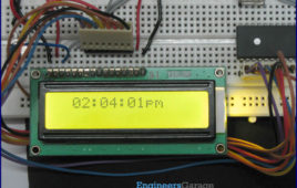
Digital clock using LCD and 8051 microcontroller
A digital clock is one that displays time digitally. The project explained here, displays time on a 16×2 LCD module. The LCD is interfaced with 8051 [[wysiwyg_imageupload::]]microcontroller (AT89C51). This circuit can be used in cars, houses, offices etc. This clock works in 12 hour mode and is configured by programming the microcontroller AT89C51. The program uses a delay function for producing a delay of 1 second.The connections in the circuit are as following: port P2 of microcontroller is used as data input port which is connected to data pins (7-14) of LCD. P3^0, P3^1 and P3^6 pins of microcontroller are connected to control pins RS, RW and EN of LCD. P1^0, P1^1, P1^2 and P1^3 pins of microcontroller are connected to tactile switches to take manual inputs. Read more to find out how to interface the clock and code the module.
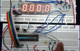
Stopwatch using 8051 microcontroller (AT89C51)
A stopwatch is a timepiece that measures the amount of time between any two occurrences. Usually, at the first occurrence, the stopwatch is started while at the [[wysiwyg_imageupload::]]second it is stopped. To use it again, a reset option is also provided with the stopwatch. The total time elapsed can thus be obtained. A stopwatch is very commonly used in racing competitions and other gaming activities. The circuit given here is a digital stopwatch that displays time on four seven segment displaysusing 8051 microcontroller (AT89C51).The stopwatch keeps the track of time the same way as a simple digital clock does. It is basically an up time counter that starts from 00:00. The control options are provided by means of tactile switches which are active low. This circuit uses three such switches for following operations. Read more to find out how the circuit is made and how 8051 microcontroller can be programmed to do the task of a stopwatch.
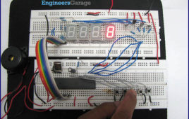
Alarm Clock using 7-Segment Display and 8051 microcontroller (AT89C51)
An alarm clock is a clock that indicates a pre-set time by producing sound at that time. This functionality of digital clock is used to awaken people or remind them [[wysiwyg_imageupload::]]of something. This circuit is an extension to the digital clock with time setting option. Here an extra switch is provided to set the alarm. While the alarm is set, the clock time does not stop and runs in the background. The project is built around the 8051 microcontroller (AT89C51). The option to set alarm is provided by providing an extra switch S5, with the microcontoller At89C51, which is made active low.Whenever S5 is pressed, the time display goes off and only 1st segment is activated. But the clock time still runs in the background. In this mode, a segment can be selected in cyclic order by pressing S2. After selecting the desired segment, its value can be changed by using S3. Once the digits and hence the alarm is set, S4 is pressed to start the clock again. As soon as the set alarm time is reached, a buzzer gets signal from the microcontroller thus producing sound.

