Summary:
Digital clock are widely used nowadays. The usual method for programming the clock as we have all seen is the ‘SOFTWARE DELAY’ or ‘POLLING’ method generated by using looping statements such as FOR and WHILE loop. But the major drawback with this type of program is that the delay of the other instructions goes on summing every time resulting in elongated delay than required. Thus after a handful amount of time, it seems as if the Clock has slowed down. To overcome this we will use Timer with interrupt to generate delay.
Description:
This project is basically divided into three parts: Controller, LCD and Keypad. The 16×2 LCD has inbuilt Hitachi’s HD44780 controller to process the data and the Keypad is configured in (4×1) fashion. This means the 4 keys are connected to four different pins having a common ground. More-over, 1 second delay is achieved by using TIMER-1 Interrupt of ATmega16.
Before taking a leap into the main program we will go through the functions of the interfaced devices.
LCD:
Here the LCD has been interfaced in 4-bit mode. To configure LCD in 4-bit mode the following three steps should be taken:
The LCD should be initialized by the command (0x28) instead of (0x38).
void lcd_int(void ) // to initialize LCD
{ lcd_cmd(0x02); // home position
lcd_cmd(0x0c); // display on, cursor off
lcd_cmd(0x28); // 4 bit lcd command
lcd_cmd(0x06); // ENTRY MODE
}
The 8-bit data/command should be masked into 4-bit i.e. higher nibble and lower nibble and then passed to the LCD.
void lcd_cmd(char x) // LCD command function to give command
{
data=0XF0&x; // higher nibble
data&=~(1<<rw); // RW=0
data&=~(1<<rs); // RS=0 , command register selected
data|=1<<en; // EN=1
_delay_ms(1); // 1ms delay for high to low pulse to latch the command
data&=~(1<<en); // EN=0
x=x<<4; // shifting lower nibble to higher nibble as pins PD4-7 are connected to the LCD
data=0XF0&x; //lower nibble
data&=~(1<<rw); // RW=0
data&=~(1<<rs); // RS=0 , command register
data|=1<<en; // EN=1
_delay_ms(1); // 1ms delay for high to low pulse to latch the command
data&=~(1<<en); // EN=0
}
As shown above, Lower nibble should always be sent following the higher nibble.
Apart from this, everything else is same as in 8-bit mode.
To display string on LCD I have made use of lcd_string ( ) function. Here, I have passed pointer type argument to the function to reduce the code memory. Alternatively, one can make use of lcd_data to display each alphabet .
void lcd_string(char *z) // to display string on LCD, used pointer
{ unsigned char i=0; // variable to increment the array element
while(z[i]!=”) // runs the loop till the array value returns null
{
lcd_data(z[i]); // displays the the data of array element on LCD
i++;
}
}
Now comes the lcd_clock () function which is used to display number directly on LCD. Here, I have used it to display time. As soon as the function is called it checks whether the passed value is zero or not. If it is ‘0’, then it displays ‘00’ at the address mentioned in the main function.
void lcd_clock(unsigned int a) // to display number(i.e. time in hr, min & sec) on LCD
{ unsigned char b=0;
if(a==0)
{
lcd_data(‘0’);
lcd_data(‘0’);
}
else
{ while(a!=0)
{
b=0x30+(a%10); // adds 0x30 to convert the number in hex
a=a/10; // to remove the last digit
lcd_data(b); // displays the stored digit
}
}
}
If the value is not zero, then the function makes use of simple loop of dividing the number by 10 and then storing the remainder of the division in one variable by using modulo (%) function. This digit is now removed from the variable by using the division (/) function and then displays by using LCD write function. You may notice that the last digit of the variable is displayed first and hence we have also used the command (0x04) which configures the cursor in auto decrement mode. So after displaying each digit the cursor shifts towards left.
For e.g. if the ‘sec’ value is 56, then the number will be displayed in the following sequence:
|
|
6 |
1.)
|
5 |
6 |
2.)
TIMER-1:
TIMER-1 is a 16-bit timer consisting of two 16 bit ‘Output Compare Register’; OCR1A and OCR1B. This means that we have two separate 16 bit timers in TIMER-1. Further, there are two timer control registers: TCCR1A and TCCR1B and one timer Interrupt register: TIMSK1 to control timer-1 interrupts.
The pin functions of both the control registers are given below:
TCCR1A:

TCCR1B:

· WGM10:13: These four bits are used to select the Waveform Generation Mode (WGM) of timer-1 along with different TOP values and its source. The TOP value is the maximum value up to which the timer can increment .The basic four Waveform Generation Modes as seen in TIMER-0 of ATmega16 are Normal mode, Clear timer on Compare Match (CTC), Phase Correct PWM Mode and Fast PWM mode. Unlike Timer-0, 16 different modes of operation can be carried out in Timer-1. Refer to the table below for brief explanation of different modes of waveform generation.

· COM1A1 and COM1A0 & COM1B1 and COM1B0: COM refers to Compare Output Mode. They are used to define the type of event when a match occurs on comparison between timer value and OCR1n (n=A/B). The table below shows different possible combinations.
For CTC Mode operation:
|
COM1A1/COM1B1 |
COM1A0/COM1B0 |
Description |
|
0 |
0 |
Normal Port Operation, OC1A/OC1B disconnected. |
|
0 |
1 |
Toggle OC1A/OC1B on compare match. |
|
1 |
0 |
Clear OC1A/OC1B on compare match (Set output to low level). |
|
1 |
1 |
Set OC1A/OC1B on compare match (Set output to high level). |
For Phase Correct PWM mode:
|
COM1A1/COM1B1 |
COM1A0/COM1B0 |
Description |
|
0 |
0 |
Normal Port Operation, OC1A/OC1B disconnected. |
|
0 |
1 |
WGM10:13 = 9 or 14: Toggle OC1A on Compare Match, OC1B disconnected (normal port operation). For all other WGM13:0 settings, normal port operation, OC1A/OC1B disconnected. |
|
1 |
0 |
Clear OC1A/OC1B on compare match when Up counting. Set OC1A/OC1B on compare match when down counting. |
|
1 |
1 |
Set OC1A/OC1B on compare match when up counting. Clear OC1A/OC1B on compare match when down counting. |
Timer and Keypad Functions
For Fast PWM Mode:
|
COM1A1/COM1B1 |
COM1A0/COM1B0 |
Description |
|
0 |
0 |
Normal port operation, OC1A/OC1B disconnected. |
|
0 |
1 |
WGM13:0 = 15: Toggle OC1A on Compare Match, OC1B disconnected (normal port operation). For all other WGM13:0 settings, normal port operation, OC1A/OC1B disconnected. |
|
1 |
0 |
Clear OC1A/OC1B on compare match, set OC1A/OC1B at BOTTOM (non-inverting) |
|
1 |
1 |
Set OC1A/OC1B on compare match, clear OC1A/OC1B at BOTTOM, (inverting mode) |
CS 10:12: These bits are specially used for prescaling the input frequency for timer. Prescaling means to choose a proper division factor. Besides this, they are also use to configure the counter input pulse. The table below explains in detail.
|
CS12 |
CS11 |
CS10 |
Description |
|
0 |
0 |
0 |
No Clock Source (timer/counter stopped).
|
|
0 |
0 |
1 |
clkI/O/1 (No prescaling) |
|
0 |
1 |
0 |
clkI/O/8 (From prescaler) |
|
0 |
1 |
1 |
clkI/O/64 (From prescaler) |
|
1 |
0 |
0 |
clkI/O/256 (From prescaler) |
|
1 |
0 |
1 |
clkI/O/1024 (From prescaler) |
|
1 |
1 |
0 |
External clock source on T1 pin. Clock on falling edge. |
|
1 |
1 |
1 |
External clock source on T1 pin. Clock on falling edge. |
OCR1A/OCR1B:
The Output Compare Registers contain a 16-bit value that is continuously compared with the counter value (TCNT1). A match can be used to generate an output compare interrupt, or to generate a waveform output on the OC1x pin.
The basic function of the timer is to generate required delay which is one second. To achieve this, I have generated 1ms delay using timer-1 in CTC mode at internal 1MHz frequency without any prescaling. For more details on timer-1, refer to TIMER-1 of ATmega16.
Moreover the program uses software interrupt of timer-1. Thus whenever a compare match occurs, timer-1 interrupt is called and the control of the program is transferred to interrupt vector location of timer-1 i.e. ISR (TIMER1_COMPA_vect) and the below written function is executed.
I have used ‘check’ and incremented to 1000 to generate 1second delay. When this is done the second increments and sequentially checks for hour and minute in the same way.
ISR(TIMER1_COMPA_vect) // TIMER-1 INTERRUPT SUBROUTINE
{ check++;
if(check==1000)
{ check=0;
sec++;
if(sec>59)
{ sec=0;
min++;
if(min>59)
{ min=0;
hr++;
if (hr==24)
{ hr=0;} } }
KEYPAD:
The keypad is interfaced to set the time of the clock as well to start it once it is set. The logic to identify the pressed key is to find out the row and column to which it belongs. Here as we have used single column keypad, the only thing we need to do is to find its row.
To carry out the above procedure irrespective of the number of keys, the pins connected to one end of the different keys are declared as output (in this case the common of all keys) and the remaining pins (in this case the first 4 pins of PORTA) are declared as input. Following this, pull up for the input pins are activated. So now, we have a supply from one end of each key.
Now we will provide ‘0’ logic level at the common of each keys to ground it. Thus, when any key will be pressed it will ground itself and the corresponding pin will read ‘0’ during this time. This means if I perform ‘AND’ operation of that particular bit (masking the remaining bits) with logic level ‘1’ , then output-‘0’ will suggest that the key is pressed and output-‘1’ will suggest that key is not pressed.
char key_scan(void)
{ DDRA=0XF0; // Configures the first 4 pins of PORTA as input and 5th pin as output
while(1) // checks continuously
{ PORTA=0B00001111; // to activate pull up for first 4 pins
_delay_ms(5);
if((PINA&0b00000001)==0) // scans the first key of row1
{ while((PINA&0b00000001)==0); // waits until the key is released
return(‘1’); // returns ‘1’ if key-1 is pressed
}}}
If the key is pressed, then due to while loop, the program will wait untill the key is released and then will return a value to the called function. As we have used four keys, I have used four if statements to check which one out the four key is pressed.
CLOCK SET FUNCTION:
This function is called as soon as the main program executes to provide the user an option to set the clock. As discussed above, four keys are used to set the second, minute and hour while the last key is used to start the clock. As the clock set uses lcd_clock () function to display numbers on the LCD I have used command (0x04) in the main function prior to calling of Clock Set function. Refer to the code.
MAIN FUNCTION:
So far we have studied all the sub-functions. Now the main functions carries out sequential execution of all the above functions as and when required. It starts by configuring different ports followed by initialization of the LCD. Then it displays a string to instruct the user to set the clock. After that it clears the display, sets the cursor into auto decrement mode and enters the clock set () function. This is followed by timer initialization and timer-1 interrupt initialization.
This completes all the work required to set the clock. Now as soon as I load the number into OCR1A register, the timer starts it works. Also, the program enters to infinite while loop which keeps the clock running. The only thing that can interrupt the while loop is Timer-1. Whenever the compare match occurs, the controller halts the normal execution and jumps to timer-1A vector location. The program at that address is executed and then transfers the control of the program to the address location where it had left.
Project Source Code
###
// Program for Digital CLock using Timer-1 Interrupt/*LCD data transfer through 4 bit modeLCD port----PORT Drs-------PD0rw-------PD1en-------PD2KEYPAD port---- PORT A>> key-1 ---- to set second>> key-2 ---- to set minute>> key-3 ---- to set hour>> key-4 ---- to start the clock*///***************************************************************************************////************************** DIGITAL CLOCK PROGRAM **********************************************//#include <avr/io.h>#define F_CPU 1000000UL#include <avr/interrupt.h>#include <util/delay.h>#define data PORTD // Defining PORTD as LCD data & command port#define rs 0 // register select pin#define rw 1 // read/write pin#define en 2 // enable pin//************************** Global variables ******************************************//unsigned int hr=0; // hour variableunsigned int min=0; // minute variableunsigned char sec=0; // second variableunsigned int check=0; // variable to count 1 sec delay//************************** LCD Sub-routines ******************************************//void lcd_cmd(char x) // LCD command function to give command{data=0XF0&x; // higher bytedata&=~(1<<rw); // RW=0data&=~(1<<rs); // RS=0 , command registerdata|=1<<en; // EN=1_delay_ms(1); // high to low pulse to latch the commanddata&=~(1<<en); // EN=0x=x<<4; // shifting lower nibble to higher nibbledata=0XF0&x; //lower bytedata&=~(1<<rw); // RW=0data&=~(1<<rs); // RS=0 , command registerdata|=1<<en; // EN=1_delay_ms(1); // high to low pulse to latch the commanddata&=~(1<<en); // EN=0}void lcd_data(char y) // LCD data function to write data on LCD{data=0XF0&y; // higher nibbledata&=~(1<<rw); // RW=0data|=1<<rs; // RS=1, data registerdata|=1<<en; // EN=1_delay_ms(1); // high to low pulse to latch the datadata&=~(1<<en); // EN=0y=y<<4; // shifting lower nibble to higher nibbledata=0XF0&y; // lower nibbledata&=~(1<<rw); // RW=0data|=1<<rs; // RS=1 , data registerdata|=1<<en; // EN=1_delay_ms(1); // high to low pulse to latch the datadata&=~(1<<en); // EN=0}void lcd_string(char *z) // to display string on LCD{unsigned char i=0; // variable to increment the array elementwhile(z[i]!='�') // runs the loop till the array value returns null{lcd_data(z[i]); // displays the the data of array element on LCDi++;}}void lcd_int() // to initialize LCD{lcd_cmd(0x02); // home positionlcd_cmd(0x0c); // display on, cursor offlcd_cmd(0x28); // 4 bit lcd commandlcd_cmd(0x06); // ENTRY MODE}void lcd_clock(unsigned int a) // to display number(i.e.time in hr,min & sec) on LCD{unsigned char b=0;if(a==0){lcd_data('0');lcd_data('0');}else{while(a!=0){b=0x30+(a%10); // adds 0x30 to convert the number in hexa=a/10; // to remove the last digitlcd_data(b); // displays the stored digits}}}//************************** TIMER1 Sub-routines ******************************************//void timer1_int(void) // to intialize timer-1{TCCR1B=(1<<WGM12); // CTC MODE operation mode of timer-1TCCR1B|=(1<<CS10); // no prescaling}void timer1_interrupt_int(void) // to intialize timer-1 interrupt{sei(); // to enable GLOBAL INTERRUPT bitTIMSK=(1<<OCIE1A); // intializing interrupt for timer-1A register}ISR(TIMER1_COMPA_vect) // TIMER-1 interrupt sub-routine to control the variables of clock{check++;if(check==1000){check=0;sec++;if(sec>59){sec=0;min++;if(min>59){min=0;hr++;if (hr==24){hr=0;}}}}}//************************** Key-pad Function ******************************************//char key_scan(void){ DDRA=0XF0; // Configures the first 4 pins of PORTA as input and 5th pin as outputwhile(1) // CHECKS CONTINUOSLY FOR THE PRESSED KEY{PORTA=0B00001111; // to activate pull up for first 4 pins_delay_ms(5);if((PINA&0b00000001)==0) // scans the first key of row1{while((PINA&0b00000001)==0); // as long as the key is pressed the while loop will not terminatereturn('1'); // returns '1' if key-1 is pressed}if((PINA&0b00000010)==0) // scans the second key of row1{while((PINA&0b00000010)==0);return('2'); // returns '2' if key-2 is pressed}if((PINA&0b00000100)==0) // scans the third key of row1{while((PINA&0b00000100)==0);return('3'); // returns '3' if key-3 is pressed}if((PINA&0b00001000==0) // scans the fourth key of row1{while((PINA&0b00001000)==0);return('4'); // returns '4' if key-4 is pressed}}}//************************** Function To Set The CLOCK ******************************************//void clock_set(void){unsigned char k=0;lcd_cmd(0x8b); //remember the cursor is in auto decrement mode so jumped to the end positionlcd_data('0'); //to display the time as "00:00:00" on lcdlcd_data('0');lcd_data(':');lcd_data('0');lcd_data('0');lcd_data(':');lcd_data('0');lcd_data('0');while(1){k=key_scan();if(k=='1') // if key-1 is pressed,{sec++; //, then it increments the second by 1lcd_cmd(0x8b); // address to display secondif(sec==60)sec=0; // if sec=60, then intialize the variable to '00' againlcd_clock(sec); // displays the value on lcd}else if(k=='2') // if key-2 is pressed,{min++; //, then it increments the minute by 1lcd_cmd(0x88); // address to display minuteif(min==60)min=0; // if min=60, then intialize the variable to '00' againlcd_clock(min);}else if(k=='3') // if key-3 is pressed,{hr++; //, then it increments the hour by 1lcd_cmd(0x85); // address to display hourif(hr==24)hr=0; // if hour=24, then intialize the variable to '00' againlcd_clock(hr);}else if(k=='4') // if key-4 is pressed,{break; // then the loop terminates and clock is ready to start}}}//************************** MAIN function **********************************************//int main(void){DDRD=0XFF; // To set the PORTD as OUTPUT port for LCDlcd_int(); // to initailize the lcdlcd_string("SET THE CLOCK:"); // Instructs the user to set the time on LCD_delay_ms(1000);lcd_cmd(0x01); // To Clear LCD_delay_ms(10); // 1 millisecond delaylcd_cmd(0x04); // To auto shift the cursor on left-side_delay_ms(10); // 1 millisecond delayclock_set(); // sets the clocktimer1_interrupt_int(); // initializes the timer1-interrupttimer1_int(); // initializes timer-1OCR1A=0x03E8; // calculated value for 1ms, starts the timerwhile(1) // infinite loop to display time continously{lcd_cmd(0x8b); // address to display secondlcd_clock(sec);lcd_cmd(0x88); // address to display minutelcd_clock(min);lcd_cmd(0x85); // address to display hourlcd_clock(hr);}}//************************************* END **********************************************//###
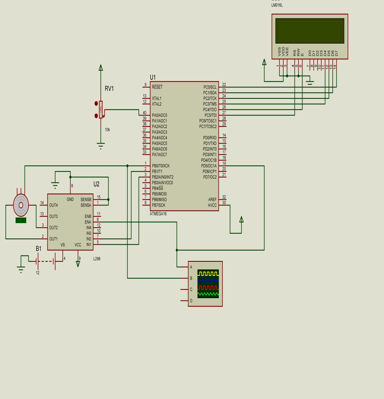
Circuit Diagrams
Project Video
Filed Under: Electronic Projects
Filed Under: Electronic Projects

Questions related to this article?
👉Ask and discuss on Electro-Tech-Online.com and EDAboard.com forums.
Tell Us What You Think!!
You must be logged in to post a comment.