Engineers Garage

  • Electronics Projects and Tutorials
    • Electronic Projects
      • Arduino Projects
      • AVR
      • Raspberry pi
      • ESP8266
      • BeagleBone
      • 8051 Microcontroller
      • ARM
      • PIC Microcontroller
      • STM32
    • Tutorials
      • Audio Electronics
      • Battery Management
      • Brainwave
      • Electric Vehicles
      • EMI/EMC/RFI
      • Hardware Filters
      • IoT tutorials
      • Power Tutorials
      • Python
      • Sensors
      • USB
      • VHDL
    • Circuit Design
    • Project Videos
    • Components
  • Articles
    • Tech Articles
    • Insight
    • Invention Stories
    • How to
    • What Is
  • News
    • Electronic Product News
    • Business News
    • Company/Start-up News
    • DIY Reviews
    • Guest Post
  • Forums
    • EDABoard.com
    • Electro-Tech-Online
    • EG Forum Archive
  • DigiKey Store
    • Cables, Wires
    • Connectors, Interconnect
    • Discrete
    • Electromechanical
    • Embedded Computers
    • Enclosures, Hardware, Office
    • Integrated Circuits (ICs)
    • Isolators
    • LED/Optoelectronics
    • Passive
    • Power, Circuit Protection
    • Programmers
    • RF, Wireless
    • Semiconductors
    • Sensors, Transducers
    • Test Products
    • Tools
  • Learn
    • eBooks/Tech Tips
    • Design Guides
    • Learning Center
    • Tech Toolboxes
    • Webinars & Digital Events
  • Resources
    • Digital Issues
    • EE Training Days
    • LEAP Awards
    • Podcasts
    • Webinars / Digital Events
    • White Papers
    • Engineering Diversity & Inclusion
    • DesignFast
  • Guest Post Guidelines
  • Advertise
  • Subscribe

Switch Status & LED with AVR microcontroller- (Part 6/46)

By Vinod Bandlamudi August 21, 2013


Generally we know about interfacing button switches, LED with Atmega32 microcontroller. We know that interface switch’s to one port, LED’s to another port and if we press any switch the corresponding LED will glow. But all the LED’s operate with single switch we don’t know.

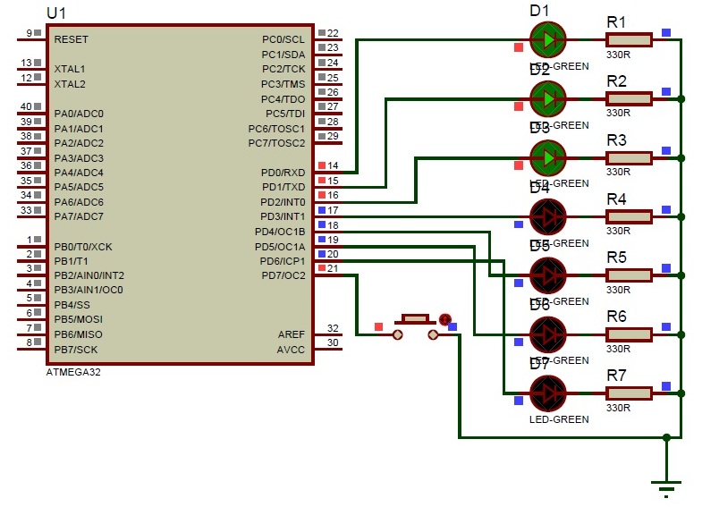
Here we are developing the program for operating 7 LED’s with one switch. The circuit connections and programming is so simple. We will discuss here about that. First we see the circuit connections. Let us take any one port of Atemga32 controller is PortD. Connect 7 LED’s to PortD and connect on switch to remaining pin of the PortD as shown in circuit diagram.

Now let us start the coding for microcontroller. First open the Atmel Studio software of any version. Create a new project with your desired file name. Here I am taking the project name as “button switch”. In the text window type the program mentioned below and we will discuss each step clearly.

#include<avr/io.h>

#include<util/delay.h>

These are the header files for Atmega32 microcontroller main function and delay function.

void pressedbutton (int a);

void releasedbutton (int b);

This is the prototype declarations for the code blocks. These are mentioned at the beginning of the program. One is for button pressed and another is for button released. Next thing ‘a’ and ‘b’ are the two integer values. We don’t know which button is pressed, so ‘a’ stores the button pressed value and as same like ‘b’ also. We don’t know which button is released, so ‘b’ reads the released button status.

                        int pressed_level[1];

                        int released_level[1];

                        int pressed[1];

                        int lednumber[1];

This is the declaration of the global variables. The variables are represented in arrays because number represents the capacity of the array. If we want to increase the buttons the array size may change according to our requirements. For example we need to add two buttons for two ports and operating the 14 LED’s we need to replace 1 with 2. Here ‘pressed’ is the global variable to store the status of pressed button. Declaring the new variable as lednumber which can represents which LED is in on position.

            Next about main function, we will have much aware about main function right…, next port initialization. Here we are taking PORTD among form the four ports. In PORTD from pin0 to pin6 we are declaring as outputs because we are interfacing LED’s to these pins only and pin7 is declaring as input because the button is connected to this pin only.

                        DDRD = 0b01111111;

                        PORTD = 0b10000000;

The above statements represent the port initialisation ‘0b’ means representing in binary values. Instead of ‘0b01111111’ we can represent with 0X7F also. The only difference is number format ‘01111111’ represents the binary value and ‘0X7F’ represents the hexadecimal value. In data direction register ‘0’ represents the input and ‘1’ represents the output. So in PORTD 7th declared as input and ‘0 to 6th’ pin declared as outputs and by using the PORT register all the pins ‘0 to 6’ make as output low and 7th pin as input high.

                        while (1)

                        {

                        }

This is loop condition that executes the condition infinite number of times.


The remaining only one thing in main function is button condition reading. We declared input pin is high in port declarations. One end of the button is connected to pin7 and another end of the button is connected to ground. At the pin side it has high value. If button is pressed that will connected to ground and the bit is cleared. That conditions we are mentioned under while loop with ‘if-else’ condition.

                        while(1)

                        {

                                    If (bit_is_clear(PIND,7))

                                    {

                                                Pressedbutton(1);

                                    }

                                    else

                                    {

                                                releasedbutton(1);

                                    }

                        }

In before we has declared the code blocks for pressed button and released button. In the above condition when ‘if’ condition is satisfied then there is a need to execute one code block. When ‘else’ condition is satisfied then there is a need to execute another code block. The prototype declaration of code blocks already mentioned in the program beginning.


void pressedbutton (int a) 

{

                                     pressed_level[a]++;

                                      if (pressed_level[a] > 500)

                                    {

                                                 if (pressed[a] == 0)

                                                {

                                                            pressed[a] = 1;

                                                             if (a == 1)

                                                             PORTD |= 1 << lednumber[a];

                                                            lednumber[a] ++;

                                                            if (lednumber[a] > 7)

                                                            {

                                                                        PORTD = 0b10000000;

                                                                        lednumber[a] = 0;

                                                            }

                                                }

                                                 pressed_level [a] = 0;

                                     }

}

When we pressed the button, the value at the pin will become 0 and then of condition satisfied and pressedbutton code block will execute. We don’t know the button value, so pressed_level value will increment and that value is greater than 500, flow forward to next step. Here I mentioned the comparison value as 500 indicates the button pressed levels. When the pressed value is equal to zero, the pressed value becomes 1, when button pressed value is equal to 1; one LED in the PORTD and next increment the LED number according button pressed. When the led number reached the 7 then turn off the all LED’s and repeat from starting.

In the above section we discussed about pressed button code block. But in stating of the program we declared two code blocks one is for pressed button and another is for released button.


void releasedbutton (int b)   

{

                                    released_level [b] ++;

                                     if (released_level [b] > 500)

                                    {

                                                pressed [b] = 0;

                                                released_level [b] = 0;

                                    }

}

Initializing the code block then we don’t know the released level of the button. So we are taking an array for storing the released button value. First increment the released level, then compare the condition for how many times the button was released and it is compared with 500. About that value we discussed in before. If the condition satisfied, pressed value is zero and released level is also zero.


Project Source Code

###


/*
 * Button_LED.c
 *
 * Created: 15-07-2013 Prince 9:06:03
 *  Author: Vinnu
 */ 
 
#include <avr/io.h>
#include <util/delay.h>
 
void pressedbutton(int a); // code block declaration for pressed button
void releasedbutton(int b); // code block declaration for released button
 
int pressed_level[1]; // global values initialization for pressed level
int released_level[1]; // global values initialization for released level 
int pressed[1]; // global values initialization to store which button is pressed
int lednumber[1]; // global values initialization for which led is on
 
int main(void)
{
DDRD = 0b01111111; // Port initialization 
PORTD = 0b10000000; //pins enabling 
 
    while(1)
    {
      if (bit_is_clear (PIND, 7)) // bit is clear at pin7 
 {
 pressedbutton(1); // code block will execute
 } 
 else
 {
 releasedbutton(1); // other wise this code block will execute
 }
    }
}
 
void pressedbutton (int a)
{
 pressed_level[a]++; // level increase one step
 if (pressed_level[a] > 500) // conditional statement
 {
 if (pressed[a] == 0) // conditional statement
 {
 pressed[a] = 1; // pressed value is equal to 1
 if (a == 1) // button pressed value is equal to 1
 PORTD |= 1 << lednumber[a]; // one led will on
 lednumber[a] ++; // led number will incremented 
 if (lednumber[a] > 7) // led number is grater than 7 repeat from starting
 {
 PORTD = 0b10000000;
 lednumber[a] = 0;
 }
 }
 pressed_level [a] = 0; // pressed level equal to zero
 }
}
 
void releasedbutton (int b)
{
released_level [b] ++; // release level incremented
if (released_level [b] > 500) // button pressed level comparison
{
pressed [b] = 0; // pressed button is become zero
released_level [b] = 0; // released level is zero
}
}
 

###


Circuit Diagrams

SwLED


Filed Under: Electronic Projects
Tagged With: atmega32, led, switch
 

Next Article

← Previous Article
Next Article →

Questions related to this article?
👉Ask and discuss on EDAboard.com and Electro-Tech-Online.com forums.


Tell Us What You Think!! Cancel reply

You must be logged in to post a comment.

EE TECH TOOLBOX

“ee
Tech Toolbox: Internet of Things
Explore practical strategies for minimizing attack surfaces, managing memory efficiently, and securing firmware. Download now to ensure your IoT implementations remain secure, efficient, and future-ready.

EE Learning Center

EE Learning Center
“engineers
EXPAND YOUR KNOWLEDGE AND STAY CONNECTED
Get the latest info on technologies, tools and strategies for EE professionals.

HAVE A QUESTION?

Have a technical question about an article or other engineering questions? Check out our engineering forums EDABoard.com and Electro-Tech-Online.com where you can get those questions asked and answered by your peers!


RSS EDABOARD.com Discussions

  • Elektronik devre
  • Powering a USB hub: safely distributing current from a shared power supply
  • RF-DC rectifier impedance matching
  • How can I get the frequency please help!
  • 12VAC to 12VDC 5A on 250ft 12AWG

RSS Electro-Tech-Online.com Discussions

  • 100uF bypass Caps?
  • Fuel Auto Shutoff
  • Actin group needed for effective PCB software tutorials
  • how to work on pcbs that are thick
  • compatible eth ports for laptop

Featured – Designing of Audio Amplifiers part 9 series

  • Basics of Audio Amplifier – 1/9
  • Designing 250 Milli Watt Audio Power Amplifier – 2/9
  • Designing 1 Watt Audio Power Amplifier – 3/9
  • Designing a Bass Boost Amplifier – 4/9
  • Designing a 6 Watt Car Audio Amplifier – 5/9
  • Design a low power amplifier for headphones- 6/9

Recent Articles

  • ITG Electronics releases gate drive transformers with 200 – 450 V DC capability
  • Stackpole introduces HCJ jumpers with 70.7 amp continuous current capability
  • Infineon releases MCU with 128K flash and multi-sense capabilities
  • ST introduces 600V GaN gate drivers with 300 ns start-up time
  • ABLIC releases S-19116 automotive voltage detector with 6.8μs response time

EE ENGINEERING TRAINING DAYS

engineering

Submit a Guest Post

submit a guest post
Engineers Garage
  • Analog IC TIps
  • Connector Tips
  • Battery Power Tips
  • DesignFast
  • EDABoard Forums
  • EE World Online
  • Electro-Tech-Online Forums
  • EV Engineering
  • Microcontroller Tips
  • Power Electronic Tips
  • Sensor Tips
  • Test and Measurement Tips
  • 5G Technology World
  • Subscribe to our newsletter
  • About Us
  • Contact Us
  • Advertise

Copyright © 2025 WTWH Media LLC. All Rights Reserved. The material on this site may not be reproduced, distributed, transmitted, cached or otherwise used, except with the prior written permission of WTWH Media
Privacy Policy

Search Engineers Garage

  • Electronics Projects and Tutorials
    • Electronic Projects
      • Arduino Projects
      • AVR
      • Raspberry pi
      • ESP8266
      • BeagleBone
      • 8051 Microcontroller
      • ARM
      • PIC Microcontroller
      • STM32
    • Tutorials
      • Audio Electronics
      • Battery Management
      • Brainwave
      • Electric Vehicles
      • EMI/EMC/RFI
      • Hardware Filters
      • IoT tutorials
      • Power Tutorials
      • Python
      • Sensors
      • USB
      • VHDL
    • Circuit Design
    • Project Videos
    • Components
  • Articles
    • Tech Articles
    • Insight
    • Invention Stories
    • How to
    • What Is
  • News
    • Electronic Product News
    • Business News
    • Company/Start-up News
    • DIY Reviews
    • Guest Post
  • Forums
    • EDABoard.com
    • Electro-Tech-Online
    • EG Forum Archive
  • DigiKey Store
    • Cables, Wires
    • Connectors, Interconnect
    • Discrete
    • Electromechanical
    • Embedded Computers
    • Enclosures, Hardware, Office
    • Integrated Circuits (ICs)
    • Isolators
    • LED/Optoelectronics
    • Passive
    • Power, Circuit Protection
    • Programmers
    • RF, Wireless
    • Semiconductors
    • Sensors, Transducers
    • Test Products
    • Tools
  • Learn
    • eBooks/Tech Tips
    • Design Guides
    • Learning Center
    • Tech Toolboxes
    • Webinars & Digital Events
  • Resources
    • Digital Issues
    • EE Training Days
    • LEAP Awards
    • Podcasts
    • Webinars / Digital Events
    • White Papers
    • Engineering Diversity & Inclusion
    • DesignFast
  • Guest Post Guidelines
  • Advertise
  • Subscribe