This tutorial is a part of series of tutorials on pwm(pulse width modulation) signal generation with stm32f103 microcontroller. Previously we looked upon how to generate pwm signal with stm32 microcontroller using keil uvision 5 ide and stm32cubemx code configurator. We moved forward on generating variable pwm signal using internal timers of stm32f103 microcontroller. We studied about generating pwm, now its time to put it in to practical and control a peripheral with the pwm signal. I decided to control a simple toy servo motor with stm32f103 microcontroller. I used two servo motors in the project for testing the code. First i used tower pro SG-90 servo motor. This motor does well but it did not move its arm at right position there is always some degrees of tolerance in actual results. You can buy one at fairly $3 price. Another motor which i just tested is HS-785HB it properly turns but requires more power(current). For this tutorial i recomend to use tower pro sg90 servo motor due to lower power consumption and simplicity.
Servo motor working principle
|
Servo motors are small motors unlike size they possess greater torque and can move heavy loads. Their small size possessing high torque made them popular among toy makers. Many toys that are around us contains servo motors in them along with dc motors. Normally servo motors in ideal state consumes little power but during load moving power shoots off and servos start consuming greater amount of current.
Servo motors works on pwm(pulse width modulated) signals. They have an arm/armature which rotates when sufficient voltage, current and pwm signal is applied to motor. When arm rotates it moves every thing that comes in its ways. |
Different types of servo motors
|
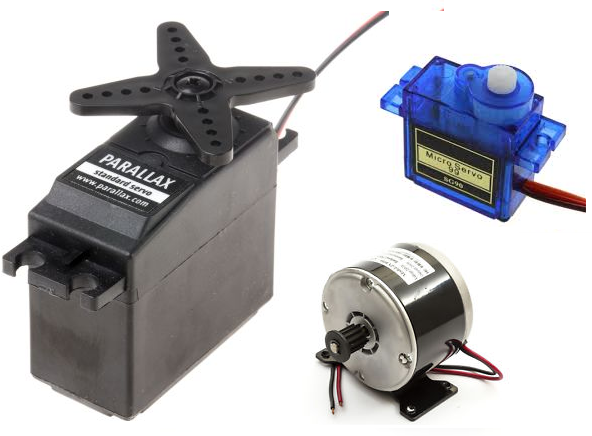
Not every servo motor can move heavy loads. It depends on their specifications and details. Normally toy servo motors can move loads from 1 kg up to 12 kg. Their are two types of servo motors DC and AC. Ac servo motors can move even mush heavier loads they are used in industrial applications. DC servo motors are best for small projects. In this project i am also using a DC servo motor with stm32 microcontroller.
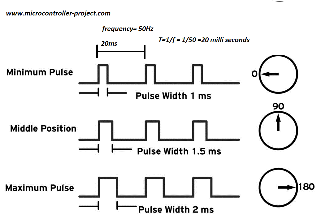
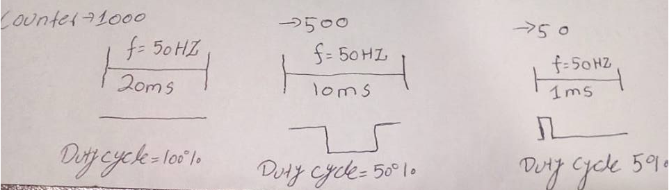
As you learned servo motors work on pwm signal. Most of the dc servo motors require 50 Hz frequency for operation with variable duty cycle. Below is the standard requirement wave forms. Our motor also require the same pattern.
As you learned servo motors work on pwm signal. Most of the dc servo motors require 50 Hz frequency for operation with variable duty cycle. Below is the standard requirement wave forms. Our motor also require the same pattern.
Servo motor pwm duty cycle and frequency requirement
At period 20 milli seconds and duty cycle 2 milli seconds servo motor arm moves to 180 degree. At duty cycle 1.5 milli seconds arm moves to 90 degree and at duty cycle 1 milli seconds arm rotates to 0 degree.
Servo with stm32 microcontroller
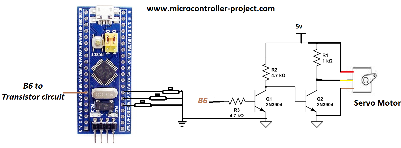
I am going to interface servo with stm32f103c8t6 microcontroller. I purchased a pre assembled and cheap board which mounts the microcontroller on it. For rotating the arm of servo motor three pins of microcontroller are used as input. For outputting pwm signal one pin is used. Port-A pins 0,1 and 2 are used as inputs and Port-B pin#6 is used to output the pwm signal.
Stm32f103 microcontroller works on 3.3 volts where as servo motor tower pro sg90 works on 5 volts. So both modules motor and microcontroller must be powered with different power sources. We can not drive servo directly with stm32 output pwm signal because its in 3.3v wave form and motor requires 5v. I inserted a circuit in between the two modules to converted 3.3v to 5v. First transistor is converting the input signal to output 5v but the signal is inverted. Another transistor inverts the inverted signal and brings it back to original logic. So now 3.3v at input cross-ponds to 5v at output to servo motor.
Stm32f103 microcontroller works on 3.3 volts where as servo motor tower pro sg90 works on 5 volts. So both modules motor and microcontroller must be powered with different power sources. We can not drive servo directly with stm32 output pwm signal because its in 3.3v wave form and motor requires 5v. I inserted a circuit in between the two modules to converted 3.3v to 5v. First transistor is converting the input signal to output 5v but the signal is inverted. Another transistor inverts the inverted signal and brings it back to original logic. So now 3.3v at input cross-ponds to 5v at output to servo motor.
Servo motor controlled with Stm32f103 microcontroller
In the above circuit make sure to common the grounds of both motor and microcontroller power supply. You can also use ULN2003 IC here instead of the two transistors. ULN2003 contains the same circuit in it with fly wheeling diodes.
In stm32cubemx initialize 3 pins Port-A pin 1,2 and 3 as input. If you do not know about how to do this then i have a simple tutorial for you on it.
Stm32f103 pwm pin settings
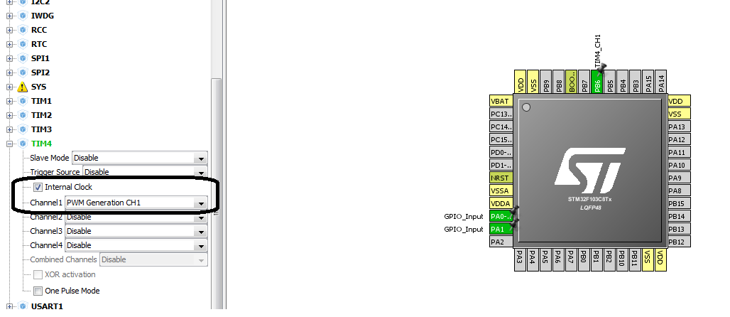
I am going to output pwm signal on PB6. For this you have to do some settings in stm32cubemx ide. Like selecting the channel and configuring some other things. Before moving any forward i would like you to take a simple tutorial on pwm pin selection and duty cycle calculation formula.
The above tutorial is very important to understand the code flow and settings below. Internal stm32 microcontroller oscillator is used in the project. Though the board has an external 8 MHz oscillator but i preferred to use internal. Final clock to timer 4 is 1 MHz.
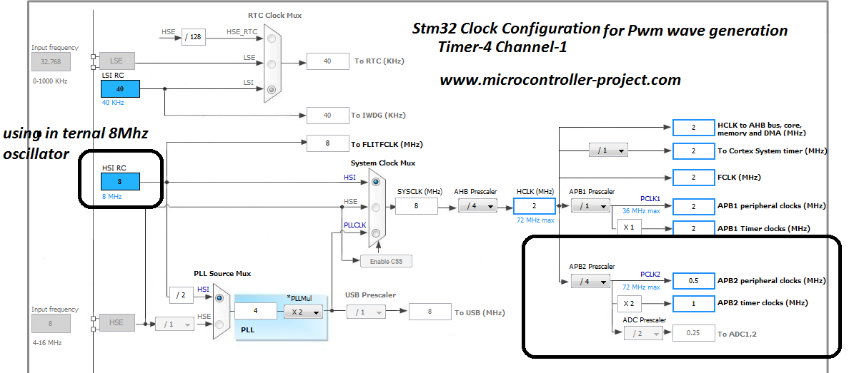
Stm32 clcok configuration for timer 4 channel 1 in stm32cubemx
Then i calculated the values for counter register and other values required to input in the timer-4 configuration. You can see the formula and other values calculations in the above tutorial.
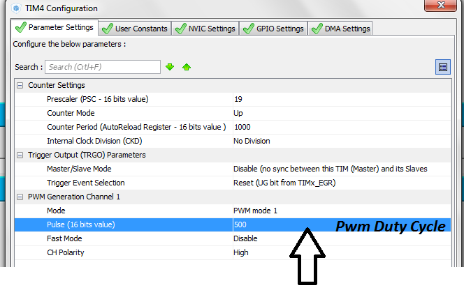
Stm32 setting pwm counter period and duty cycle in stm32cubemx
My counter period is 1000. It means at 1000 the pwm duty cycle will be 100% with period 20 milli seconds or 50 Hz frequency. At 500 pwm duty cycle will be 50% which translates to 10 milli seconds. At 5% it will be 1 milli second and at 10% it will be 2 milli seconds and at 7.5% it will be 1.5 milli seconds.
This counter value is used in code to move the servo motor arm. Below is the code. When button-3 is pressed motor moves to 180 degrees. When button-2 is pressed button rotates to 90 degree and when button-1 is pressed it comes back to 0 degrees.
Internal pull up resistors of pins Port-A Pin# 1,2 and 3 are activated. Hence only buttons are connected to ground directly.
Download the project code. Code is written in keil uvision 5 ide. Stm32cubemx is used for microcontroller configuration. Code folder contains all keil and stm32cubemx files. Code is open source you can modify and use it according to your needs. Please provide us your feed back on the project.
You may also like:


Filed Under: Electronic Projects, Featured Contributions, STM32, STM32.

Questions related to this article?
👉Ask and discuss on Electro-Tech-Online.com and EDAboard.com forums.
Tell Us What You Think!!
You must be logged in to post a comment.