Waking up isn’t always easy, especially when the snooze button is typically only a short reach away. Overcoming the desire to stay in the comfort of our beds often requires an understanding of intrinsic motivation. But we have a solution that requires one simple device — a smart mat.
In this project, we’ll design a smart mat that will work as a morning alarm clock. It not only sounds an alarm but helps inspire you to overcome that morning procrastination of getting out of bed.
We’ll design a prototype for a smart mat with the necessary electronics to ensure you get up for the day easily. It keeps time and sounds the alarm, which can be programmed from a mobile app. You’ll need a mat and a microcontroller with Bluetooth and WiFi functionality. We use ESP32. A push button and a buzzer are also required. Let’s get started.
Components required
1. ESP32 x1
2. Push buttons x as required
3. Buzzer x1
4. Regular mat x1
Circuit connections
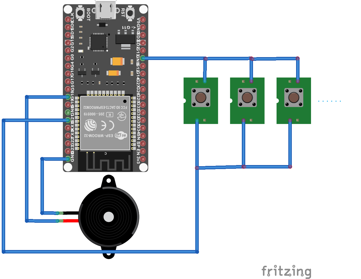
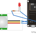
A regular mat that can be torn into two layers is needed to get started (the electronics go inside). Prepare an array of push buttons, all connected in parallel and neatly arranged at equal distances from one another over the shape of the mat, as shown in the image below.

Attach square pieces of a thin plastic sheet or acrylic sheet to the top of the push buttons using glue to form the middle layer. So, when a force is applied on the plastic sheet square, the button is pressed.

The array of push buttons forms the middle layer of the mat. If someone stands on it, multiple buttons will be pressed, and this will short the two wires that connect all of the push buttons in parallel. One of these wires connects to ESP32’s Ground pin, and the other connects to ESP32’s GPIO21 pin.
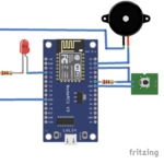
A buzzer is attached to ESP32 by connecting one of its terminals to the GND and the other to ESP32’s GPIO 18 pin. After making all the connections, the smart mat should look like the circuit diagram below.
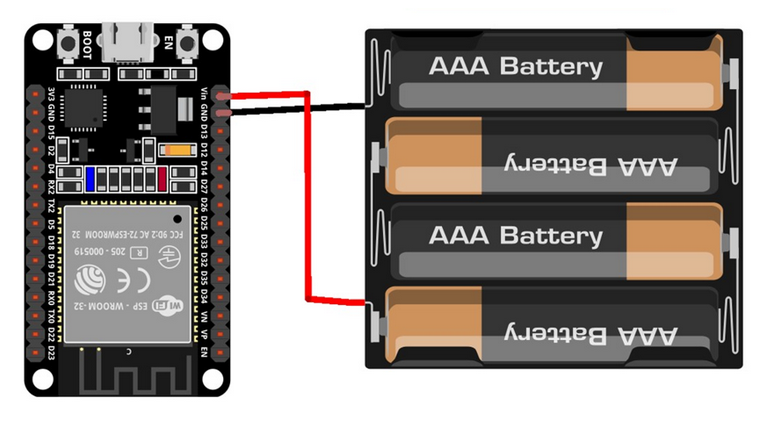
The smart mat’s microcontroller circuit is powered by 6A/9A AAA batteries as shown below.
Before installing ESP32 into the mat’s circuit, remember to upload the sketch.
Arduino sketch
Remember to replace the SSID and network key with those of your own WiFi connection.
Mobile application
The alarm is set in the smart mat using a mobile application built using the MIT App Inventor. Login to MIT App Inventor and build a user interface in the Designer as shown below.
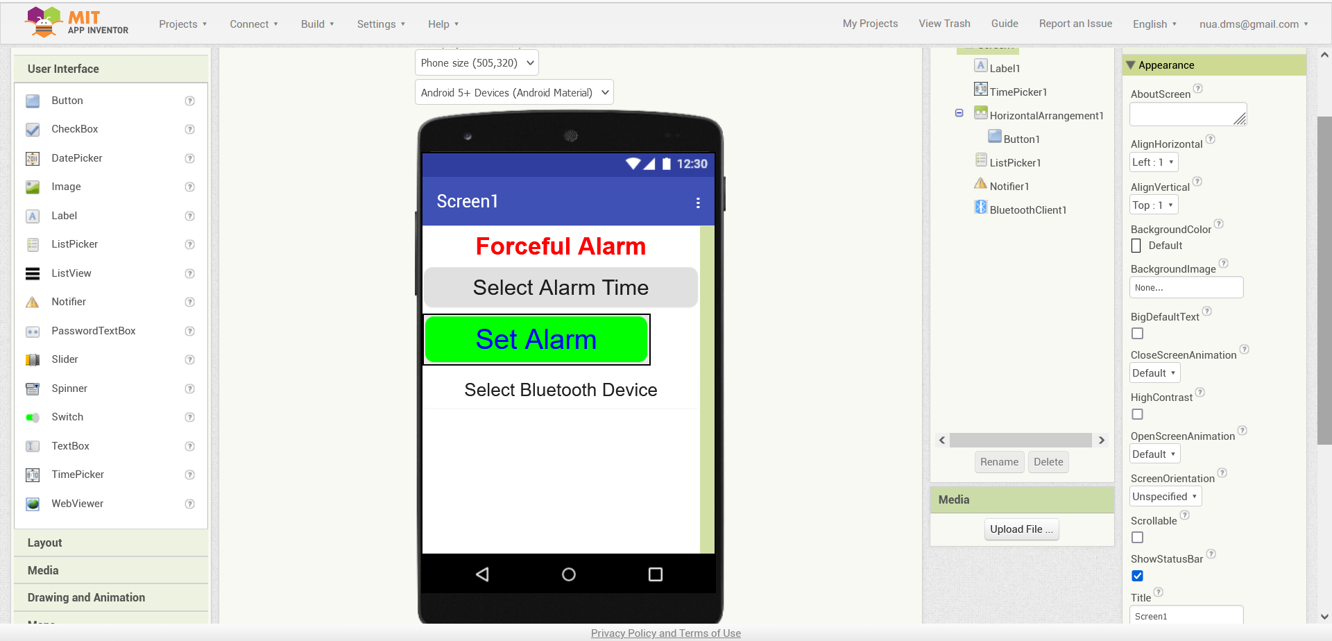
The application is built using following components in MIT App Inventor…
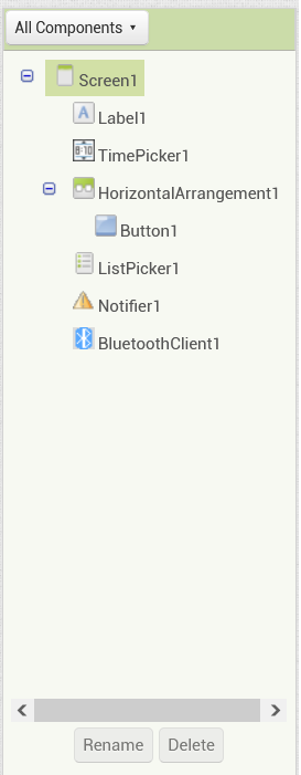
The properties of Label1 are set as shown below.
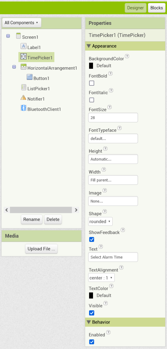
 The properties of the TimePicker1 are set as shown below.
 The properties of the HorizontalArragement1 are set as shown below.

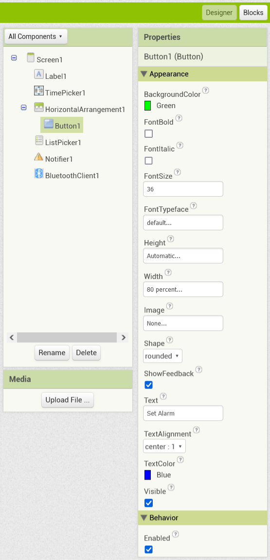
The properties of Button1 are set as shown below.
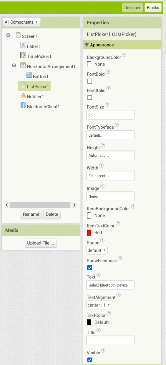
 The properties of the ListPicker1 are set as shown below.
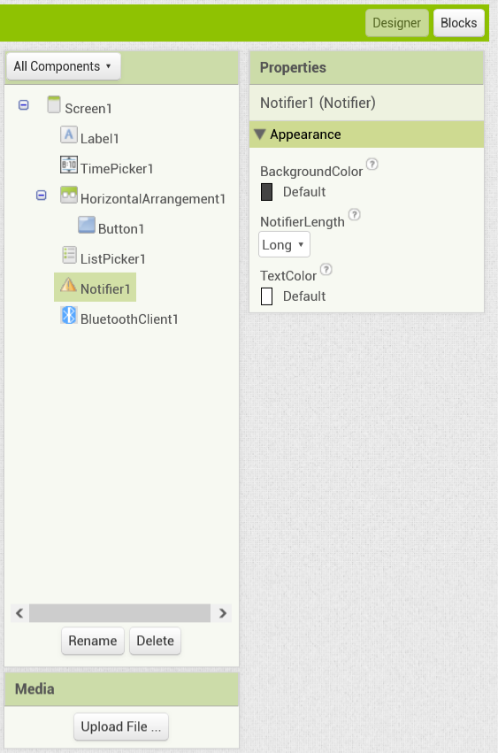
 The properties of the Notifier1 are set, as shown below.
The properties of BluetoothClient1 is set as shown below.

The logic of the app is defined in the block editor as shown below.

The mobile app allows users to set an alarm that’s in the smart mat. To do so, select the Bluetooth device button and the “Smart Wakeup Alarm Mat.” The smart mat is viewed in the app as a Bluetooth device and the button’s text will change to “Connected” once selected.
To set an alarm from the app, simply tap the time picker and select a time for the alarm to sound. Next, press the “Set Alarm” button to set it. The process is demonstrated in the following video.
How project works
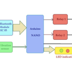
To set an alarm in your smart mat, use MIT App Inventor’s mobile app builder. This application lets users use their smart mat as a Bluetooth device. When an alarm is set using the app, the hour and minute values (in a 24-hour format) are sent to ESP32 over Bluetooth as a comma-separated pair of values.
ESP32 continuously searches for if the alarm is set. If not, it will continue to time-keep by polling the current time from the NTP server. ESP32 must be connected to a WiFi network. The SSID and password for this are hard-coded in the sketch.
If an alarm is set, ESP32 will compare the current time based on the NTP server with the time set for the alarm. When the hour and minute values match between the current time and alarm time, the alarm is triggered, and the buzzer rings. The alarm continues until the user steps on the mat. This requires them to get out of bed!
When the user steps on the mat, the push buttons are pressed down, shorting the two wires that connect all the buttons in parallel. ESP32 stops playing the alarm as a LOW signal is received from the button network at GPIO21.
The code
The sketch begins with BluetoothSerial.h, WiFi.h, NTPClient.h, and WiFiUdp.h. If any of these libraries are not found, install them using the library manager.
Here’s a summary of what each one does in this project:
- BluetoothSerial.h manages the smart mat (or ESP32) WiFi connection with the mobile application.
- WiFi.h manages the Wi-Fi connection with the home Wi-Fi network.
- NTPClient.h connects with the online NTP server.
- WiFiUdp.h manages the UDP connection over Wi-Fi.
Afterward, notes for the buzzer are defined, as are the variables are also defined for each pin assignment for the buzzer and the button array. The variables to track the status of the button array, SSID, Wi-Fi network key, current time, hours value, minutes value, seconds value, alarm hours value, alarm minutes value, alarm status, and alarm shutdown status are also defined. Then, the objects of WiFiUdp, NTP client, and Bluetooth Serial are initialized.
In the setup() function, the pin interfaced to the button array is set as a digital input. The baud rate for the serial communication to debug messages to the serial console is set to 115200. The Bluetooth is initialized with name “Smart Wakeup Alarm Mat.”
ESP32 connects to the Wi-Fi network and the NTP client is initialized and configured for the correct time zone.
The user-defined function stringToCharArray() is defined to extract values from the string data received over Bluetooth and Wi-Fi networks. The function playAlarm() signals the alarm by setting off the buzzer. The function senseInput() detects if the button array is pressed and if so, it shuts off the alarm.
In the loop() function, ESP32 uses a Bluetooth connection to search for the data received from the mobile app. If data is received, the alarm is set, and its hour and minute values are stored. The status of the alarm is set to TRUE, and the status for the alarm to shut off is set to FALSE.
It then retrieves the current time from the NTP server and extracts the current hour and minute values. These values are compared with those of the set alarm. If they match, the alarm is triggered. The alarm does not turn off until the button array is pressed by stepping over on the mat.
Results
This image shows a compilation of the debug messages received from the smart wakeup alarm mat.

You may also like:


Filed Under: Electronic Projects, ESP8266.

Questions related to this article?
👉Ask and discuss on Electro-Tech-Online.com and EDAboard.com forums.
Tell Us What You Think!!
You must be logged in to post a comment.