ESP8266 is a UART to WiFi module which provides an easy way to connect any small Microcontroller platform like Arduino to Internet wirelessly. Since ESP8266 super cheap, and super easy to work with it become one of the leading platforms for the Internet of Things. You can use AT commands to connect to WiFi networks and open TCP connections without running TCP/IP stack. It also includes 32Bit Microcontroller which can be programmed to act as a standalone WiFi connected Embedded Platform.
If you are new to this refer Getting Started with ESP8266.
The ESP8266 has 3 modes:
ST – Station mode in which ESP acts as a WiFi node and connect to an existing Access point.
AP – Access Point mode where the ESP acts as AP & other devices can connect to it.
ST & AP – Acts as both Station and Access point mode.
AT+CWMODE=x is the command used for configuring the mode of operation.
Where, X can be 1 for ST mode, 2 for AP mode & 3 for both.
Here it is configured as Station mode by the command AT+CWMODE=1.
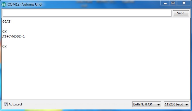
Fig. 1: Screenshot of AT+CWMODE Command passed from Arduino Serial Terminal to ESP8266
To start the communication, we need to configure a server within the ESP module.
Use the below command to set the multiple connections.
AT+CIPMUX=1
Use the below command to initialize an HTTP port 80 server.
AT+CIPSERVER=1,80
To know the IP address of the module after the successful connection, use the command AT+CIFSR it will give the IP address.
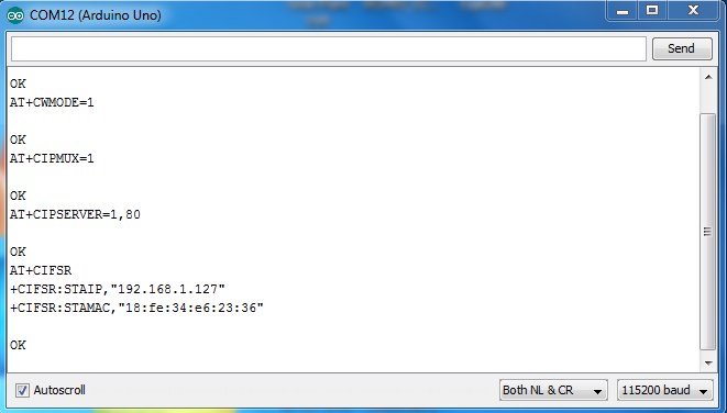
Fig. 2: Screenshot of AT+CIFSR Command passed from Arduino Serial Terminal to ESP8266
We will get two IP address if we initialize our module in Dual mode by configuring CWMODE to 3, which can work simultaneously. Open the Station IP address in the web browser.
Note: PC should also connect to the same Access Point.
When the Station IP address is entered and tried to connect, the browser will send an HTTP GET request to the module which is printed on the serial port monitor. The IP address of requesting Host PC and the browser name will be displayed.
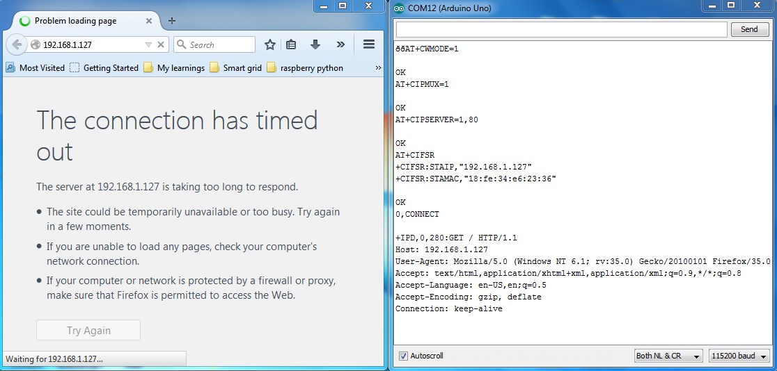
Fig. 3: Screenshot of HTTP GET Request from Browser
Type the below command after you get OK.
AT+CIPSEND=0,30
Here, 30 denotes the number of characters you are going to send through the channel 0. Use the same channel number which is shown in the browser request received.
Now you will get a > symbol after this you have to type 30 characters to be sent.
The module will not send the data until you type 30 characters, it will send the data once you completed entering and acknowledge by showing SEND OK.
There is also Timeout limit you have to enter characters before the time limit to avoid disconnection.
At this stage, even though characters are sent to the browser it will wait for the channel to be closed.
Type in AT+CIPCLOSE=0 to close the connection where “0” is the channel number we used to initialize the connection.
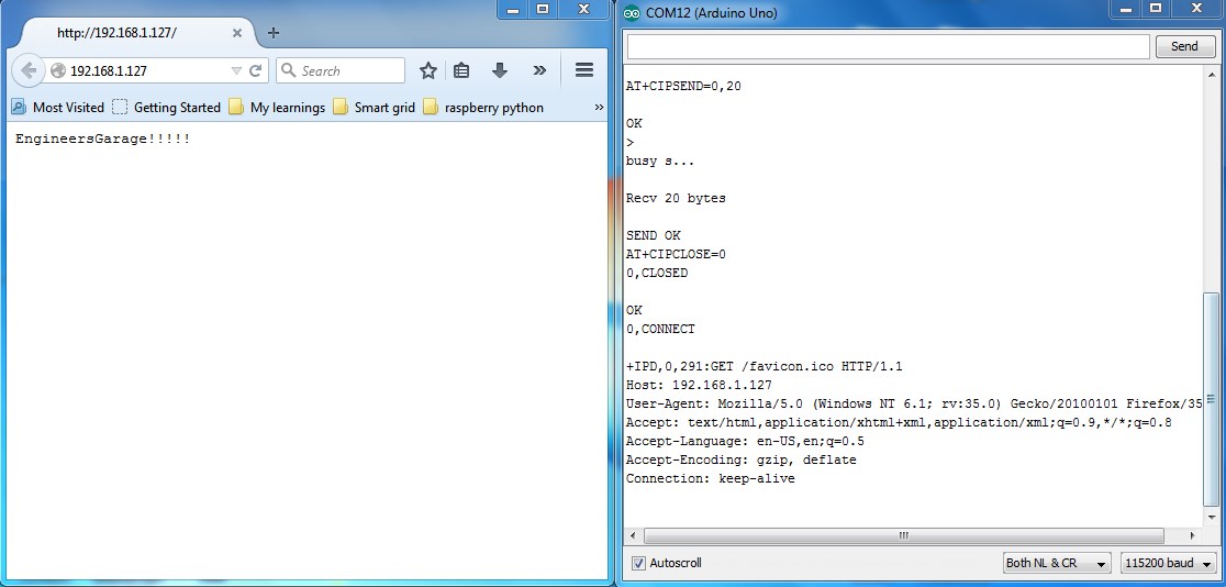
Fig. 4: Screenshot of AT+CIPCLOSE Command passed from Arduino Serial Terminal to ESP8266
Two way communication is also possible with this module, to test this open PUTTY and select the connection type as TELNET and port to 80.
Enter the module IP address in the address field and click open.
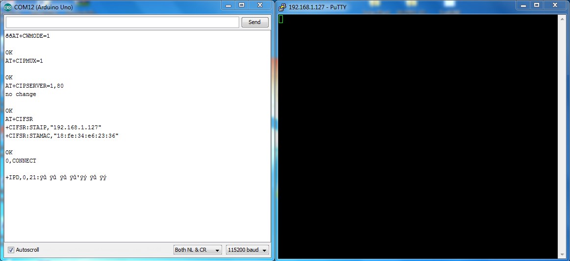
Fig. 5: Screenshot of Entering the Module IP Address in the Address Field of TELNET Window
Type some characters inside TELNET window and press Enter you will get displayed in the ESP8266 serial window.
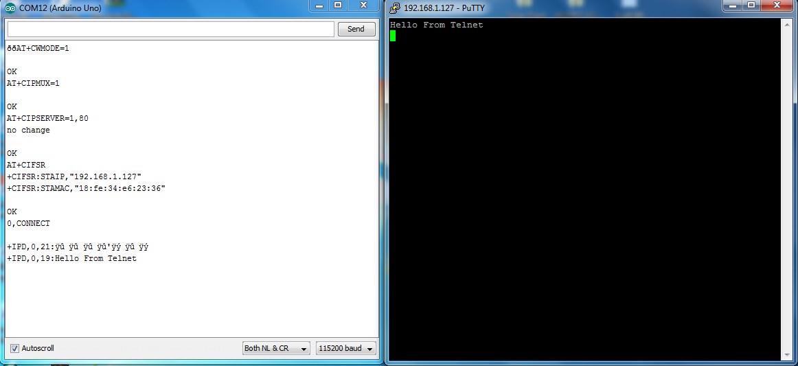
Fig. 6: Screenshot of Response in TELNET Window
+IPD,0,19:Hello….
Where, 0 is the channel number & 19 is the number of characters received.
Type AT+CIPSEND=0,20 in the ESP Serial window and enter the 20 characters as previously done in the browser communication. You can see the characters received in TELNET.
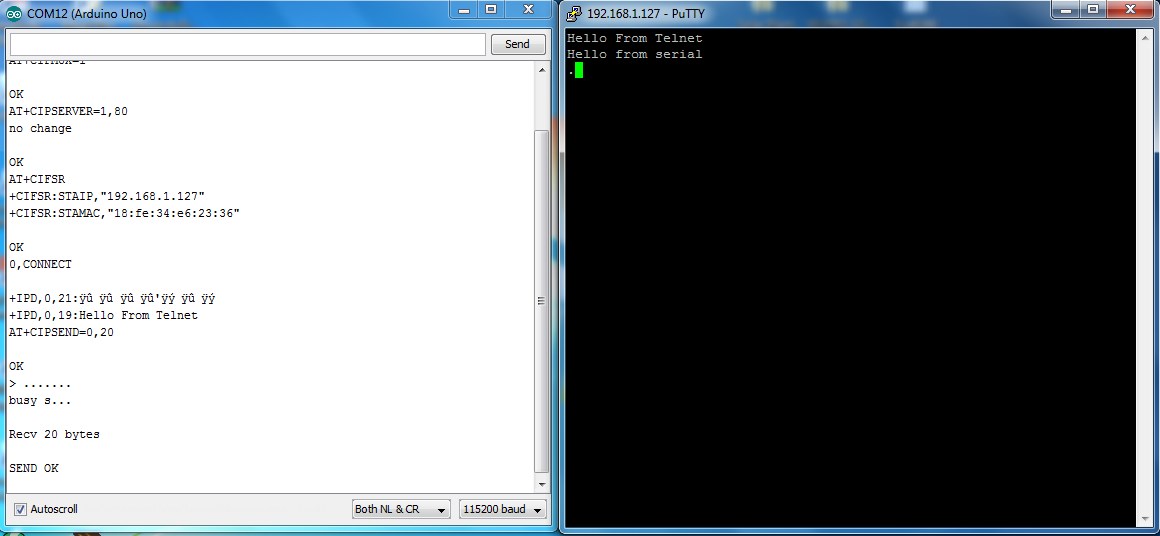
Fig. 7: Screenshot of AT+CIPSEND command Passed from Arduino Serial Terminal to ESP8266
Filed Under: Tutorials

Questions related to this article?
👉Ask and discuss on EDAboard.com and Electro-Tech-Online.com forums.
Tell Us What You Think!!
You must be logged in to post a comment.