Many of us have modular kitchen which have chimney to extract smoke out so that smell of smoke will not fill in kitchen and avoids the harmful effects of smoke on furniture and kitchen utensils. But sometimes it happens we forget to switch on the chimney which results in smoke in kitchen and sometimes we forget to off the chimney leading to the wastage of electricity and money. So to solve this problem we have described a circuit which will switch on the fan automatically when smoke reaches to point and off the fan automatically.
You can also use this circuit while soldering because as we know solder fumes are not good for health so it will on the fan to extract the smoke present in room leaving smoke free area.
[[wysiwyg_imageupload:11148:]]
Fig. 1: Prototype of Exhaust Fan Circuit on Breadboard
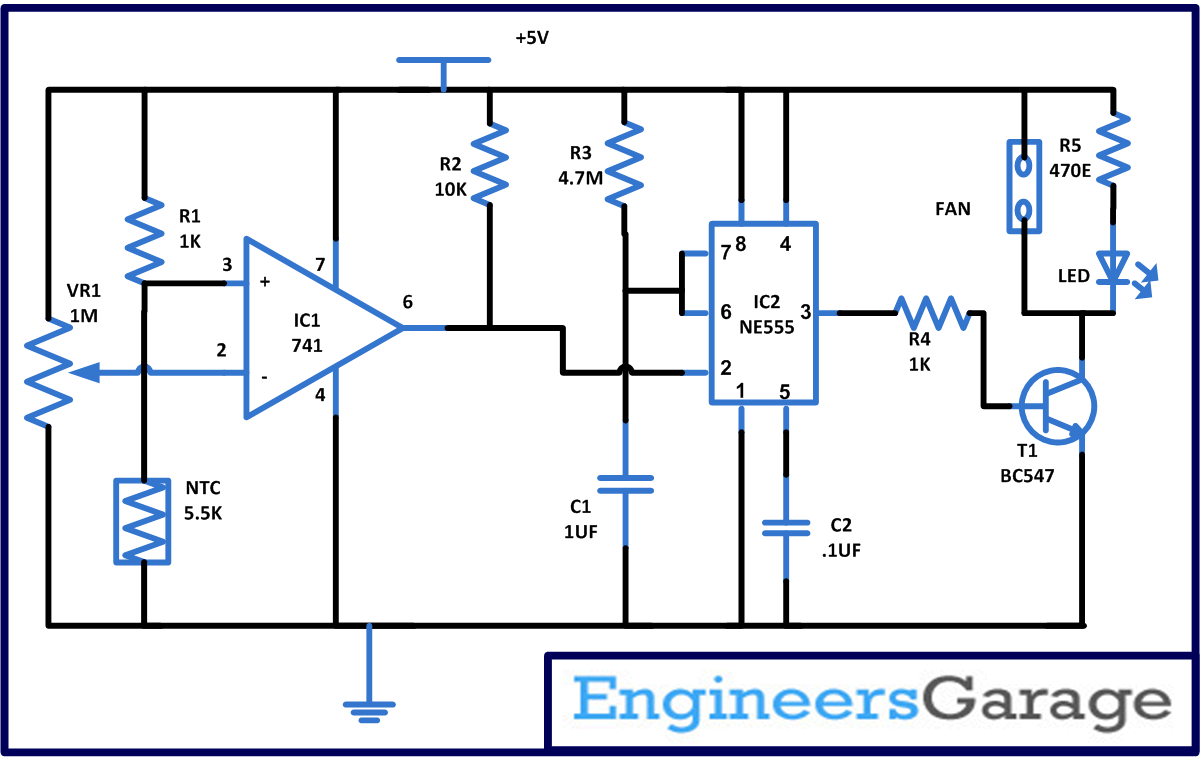
This simple exhaust fan circuit is based on two ICs namely the 741 which works as a comparator here and NE555 timer IC which is wired in mono-stable mode and we are using a Negative Temperature Coefficient (NTC) as a sensor with few more common and readily available components.
 Basically, thermistor is a special kind of resistor whose resistance varies with the temperature. There are two kinds of thermistors one is NTC and another is PTC. Thermistors are made with the help of semiconductor material and work on the theory of electron-hole pair. As the temperature of semiconductors increases the electron-hole pair generation also increases and this increase in electron hole pair drop the resistance and current flow increases. Therefore if resistance increases with increase in temperature it is call PTC. And if resistance decreases with increase in temperature it is called NTC. In the circuit describe below we are using NTC of 5.5K.
Working of exhaust fan circuit
First of all assemble the circuit carefully in a compact unit and place the sensor near to the chimney or near to solder iron stand so that it can easily senses the change in temperature due to smoke.
Now from the circuit you can see that we have made the pin 3 (non inverting) of IC1 high with the help of potential divider build with the help of resistor R1 and NTC. And pin 2 (inverting pin) is used to set the reference voltage with the help of VR1.
Initially when you on the circuit pin 6 of IC1 is held high and this is connected to pin 2 of IC2 which is also held high through resistor R2. Therefore at this time output of IC2 is low and it will cut of the transistor T1 and fan will remain off. Resistor R4 will prevent the excessive base current from flowing into the transistor.
Now adjust the voltage at non inverting pin 3 more than voltage at inverting pin 2 and bring the hot iron near to the thermistor. Because of hot soldering iron the resistance of thermistor NTC will fall. And a stage will come when voltage at pin 3 is less than voltage at pin 2. This will make the output pin 6 of IC1 to go from high to low state which will trigger the momostable multivibrator and pin 3 of IC2 goes high to make the transistor into conduction and the fan connected to it start rotating and LED connected at output also start blinking.
Fan will continuous to rotate until solder iron is place and when you remove the solder iron it will rotate for fix duration of time. The time duration for which it will on the fan depends upon the resistor R3 and capacitor C1.
Circuit Diagrams
Project Components
Project Video
Filed Under: 555 Timers, Circuit Design
Filed Under: 555 Timers, Circuit Design


Questions related to this article?
👉Ask and discuss on Electro-Tech-Online.com and EDAboard.com forums.
Tell Us What You Think!!
You must be logged in to post a comment.