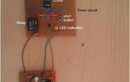
Many of us have modular kitchen which have chimney to extract smoke out so that smell of smoke will not fill in kitchen and avoids the harmful effects of smoke on furniture and kitchen utensils. But sometimes it happens we forget to switch on the chimney which results in smoke in kitchen and sometimes we forget to off the chimney leading to the wastage of electricity and money. So to solve this problem we have described a circuit which will switch on the fan automatically when smoke reaches to point and off the fan automatically.You can also use this circuit while soldering because as we know solder fumes are not good for health so it will on the fan to extract the smoke present in room leaving smoke free area.
Shooting Game Using IC555
This is a simple shooting game comprising of an infrared pulse emitter and receiver. There are 8 white leds and one green led which will light up periodically. The player has to shoot at the receiver when the green led lights up. This is a simple beginner’s project and can be used to make more complicated projects like “LASER TAG GAME”. Infrared gun (transmitter) for this electronic game is built around IC1 timer (NE555) wired as an astable multivibrator with a centre frequency of about 35 kHz. The receiver circuit has 3 main ICs – 2 NE555s (one wired as an astable multivibrator and the other for monostable operation) and 1 CD4017B (decade counter). These circuits can be modified to make “LASER TAG GAME”. Read more to find out how IC555 is used in this circuit and how it works.
Timer Operated Relay with Digital Display
The circuit presented here operates a relay for Fixed Timer Interval. So the device or machine connected with relay operates for same time. The device once switched ON, automatically switches OFF after Fixed (set) Time Interval when relay switches OFF. The Time Interval can be varied and it is displayed on 7 Segment Display. This kind of circuits can be used in many applications where it is required to operate any device or machine for Fixed Time Interval.
8 LED Flasher with Flashing Speed Control
The 8-LED Flasher is built around Timer and Counter ICs. It Flashes 8 LEDs sequentially and the flashing speed can be controlled by a potentiometer. This can be used as a design pattern for decoration. But theoretically, it clears the Timer and Counter concepts in an easy way.The circuit comprises of various components like 555 Timer IC, Decade counter (CD4017), LEDs, Resistors, Capacitors, Wires & a 9V battery. The monolithic integrated circuit 555 timer can be used as square-wave generator, linear saw-tooth generator, pulse generator, time delay generator, etc. here we use it to generate square waveform i.e. it is used in the Astable Mode with a duty cycle of 66.6%.The 8 LEDs could be arranged in any pattern and thus be used as a decorative Light Toy in your living room.
Parental Control
Children like to watch cartoons movies or any other their favourite show on the television and do not pay attention on their studies even at the time of examination. So to keep eye on children we have design a parental control device. When the children in your home hold the remote of the television to on the TV or want to change channel and press any button of the remote then a loud sound would be generated by the device. And these will let you know that your child has tried to switch on the TV. The main advantage of these circuit is that you can easily do your work without any trouble as it produces loud noise so you can hear the noise while working in the kitchen or while sitting in the nearby room.
Simple DC Motor Controller using 555 Timer IC
Controller is actually a combination of two circuits – driver circuit and Switching circuit. Driver is the actual circuit that drives DC motor and switching circuit decides how DC motor should be driven. So actually, switching circuit is the main circuit that controls the motor. Now there are two parameters of DC motor that can be controlled Speed and Direction.Changing the direction of DC motor is very simple just reverse the supply given to DC motor. For varying speed of motor you have to vary the applied DC voltage. One well known method widely used in industries is Pulse Width Modulated (PWM) speed control of DC motor also known as chopper control.
8 LED Flasher with Flashing Speed Control
The 8-LED Flasher is built around Timer and Counter ICs. It Flashes 8 LEDs sequentially and the flashing speed can be controlled by a potentiometer. This can be used as a design pattern for decoration. But theoretically, it clears the Timer and Counter concepts in an easy way.The circuit comprises of various components like 555 Timer IC, Decade counter (CD4017), LEDs, Resistors, Capacitors, Wires & a 9V battery. The monolithic integrated circuit 555 timer can be used as square-wave generator, linear saw-tooth generator, pulse generator, time delay generator, etc. here we use it to generate square waveform i.e. it is used in the Astable Mode with a duty cycle of 66.6%.The 8 LEDs could be arranged in any pattern and thus be used as a decorative Light Toy in your living room.
Generating time delay using astable mode of 555 timer IC
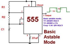
This circuit based project demonstrates the working of 555 timer in astable mode to generate pulses of time period 0.5 second. This pulse can be further used [[wysiwyg_imageupload::]]for anything where we need a pulse such as to blink a LED or to create fashionable blinking lights. This circuit of this project makes the use of timer IC NE555 which produces a constant square pulse of a desired frequency. This pulse could be either triggered or could be produced continuously depending upon the mode of 555 we are using. The two mostly used modes of 555 are Monostable and Astable. Here it is used in the astable mode with time period of half second, with high time period of 0.333 seconds and low time period of 0.166 seconds. Keep on reading to find out how the circuit is constructed and in what mode does the 555 IC works.
Light dependent frequency variation using LDR
This circuit responds to the change in light illumination in the form of varying frequency which can be observed through a flashing LED as output. The idea of [[wysiwyg_imageupload::]]this project is to use an LDR in place of a fixed value resistor which in turn generates a particular frequency. The generated frequency corresponds to the light conditions of the ambience.This concept finds popular application in motor speed control where the output is connected to motor driver circuit. Disco light is another interesting application of the idea where the lighting pattern keeps on changing. The circuit of this project uses NE555 to generate a continuous series of pulses in astable mode. The frequency of these pulses is obtained based on values of two resistors and a capacitor. Keep on reading to find out more information on the circuit and its working.
Negative supply using 555 IC
This circuit and project demonstrates the application of 555 to generate negative supply. The negative supply produced is about 3 volts lesser than the applied [[wysiwyg_imageupload::]]voltage due to various losses. At times the circuit requires both negative and positive supply, which is not available in the batteries. IC555 includes two comparators, one RS flip-flop and other few discrete components like transistors, resistors etc. The biasing voltage (Vcc) is divided in three parts through voltage divider using same value of resistors R. from these 1/3 Vcc is given to non inverting terminal of trigger comparator and 2/3 Vcc is given to inverting terminal of threshold comparator. The outputs of both comparators are given to R and S inputs of flip-flop. The Q’ output is actual output of IC and Q output drives. In this project, 555 work in astable mode and produces a frequency of about 663 hertz.
Day and Night Indicator using IC 555
The main aim of the Day and Night Indicator project is to help us to turn on the lights as the night falls automatically and as the dawn sets in the Day and Night Indicator automatically gets switches off the light and plays a musical morning wake up alarm. Another feature of the project is that at the time of no light in the room during night the night lamp gets turned on automatically. With the help of this circuit you are not required to switch on or off the lights in nights or in the morning.
Simple RPM Counter using IC 555
RPM counters are used to measure Speed of Motors (AC/DC) or any Rotating Object. They measures and indicates current Rotating Speed of Motor. They are very essential in applications like Speed Control of Motors and close Loop Control System. Such industrial RPM counters are very accurate made up of microcontroller or microprocessor.
DIY: LASER Based Pulse Transmitter and Receiver
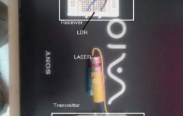
The circuit presented here transmits pulses wirelessly to long distance (more than 20 meter) using keychain LASER (readily available in market). A transmitter generates continuous pulses that are fed to LASER. LASER blinks at the rate of pulse frequency and emits light pulses. LDR on the receiver side, detects this light pulses and reproduces it at the output. So the same pulses that are generated at transmitter side can be received at receiver side to longer distance.To begin with the first thing that is required for this project is to prepare LASER. So let us start with how to prepare a LASER. LASER key-chains available in the market are like this. To prepare it for the project we need to take out its anode and cathode terminals to provide pulses. In order to remove button cells and keychain part from backside of the keychain. You will see one small spring, which is cathode terminal. Connect one wire with this as shown in the figure below.
ASK Modulator using 555 Timer IC
ASK means Amplitude Shift Keying (also known as ON-OFF keying). It’s one of the Modulation Scheme used to transmit Digital Data using High Frequency carrier signal. It’s very simple and popular method. It transmits 1’s and 0’s of Digital Data by transmitting carrier or no carrier like · Bit 1 (logic high) is Transmitted with carrier frequency Fc· Bit 0 (logic low) is Transmitted with no carrierMeans series of bits – bit stream is transmitted as carrier ON and carrier OFF. That’s why it is also known as ON-OFF keying.
DIY : Short Range Optical Pulse Transmitter and Receiver
This project demonstrates how pulses can be transmitted from one place to another place wirelessly using light as medium. One LED is connected at the transmitter side that blinks at frequency of applied pulses. At the receiver side, Light Dependent Resistor (LDR) is used to receive light pulses. IC555 is used at both ends. At transmitter side it is used to generate continuous pulses with variable frequency output from 1 Hz to 10 Hz. At receiver side it is used to generate same pulses as per the trigger input applied by LDR. Note – for visual effect (demonstration) the pulse frequency is kept low. The frequency can be kept high in terms of KHz also.
Simple Stepper Motor Driver using 555 Timer IC
The circuit presented here rotates stepper motor and varies its RPM (speed). It does not use any micro controller (or micro processor) or any programmable digital device also it does not require any software program to generate sequence of pulses. It drives stepper motor using simple, easily available and commonly used components and ICs like IC555, decade counter, OR gate, current driver chip etc. That is why the name given simple stepper motor driver.
Simple 2 Digit Auto-Manual Counter
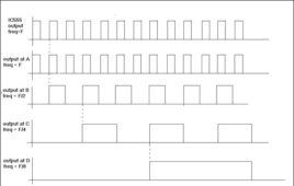
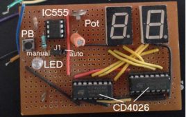
The circuit presented here counts from 00 to 99 and displays it on two seven segment displays. It can work as free running counter in auto mode or it can count manually when button is pressed. In auto mode it gets continuous pulses and counts continuously at a rate of 1 Hz. That means the count is updated at every second or in other words counter displays time in seconds. This counting rate can be changed by changing pulse frequency. In manual mode, the count is incremented when push button is pressed manually. So it can be used to count up to 100 (from 0 to 99) as per manual requirement.The counter circuit is made up of decade counter cum display driver chip CD4026. The pulse circuit is build using IC555. The circuit can be used in many applications like object counter, frequency counter, RPM counter, stop watch timer, token count display and many others.
Auto and Manual Pulse Generator
Many devices require input pulses for their operation. Some device requires continuous train of pulses some requires single pulse. In some of the devices there is a provision to alter between continuous pulses and single pulse. For example a stepper motor controller can have two operating modes – auto and manual. In auto mode it requires continuous pulses to rotate motor continuously while in manual mode it requires single pulse to be generated when button is pressed manually.The circuit presented here is 2 in 1 circuit that generates low frequency pulses in the output. It has two operating modes. In auto mode it generates pulses continuously and in manual mode it generates pulse when push button is pressed. The circuit is built using single IC555. To generate continuous pulses it is configured in astable mode and to generate single pulse it is configured in monostable mode.
Remote Control for Devices using Cell Phone
Many of us face problem when we out of our home like if we want to on the motor, so that when we reach home water will be filled in over head tank or we want to on other appliances like light fan etc. Hence to solve this problem we have describe a simple circuit which will on your device or appliances remotely and it will become off automatically after preset time interval. Many circuits have been developed so far to solve this problem but main advantage of this circuit is uses readily available components and this circuit is not expensive as well because this circuit is made using without microcontroller.
Reaction Timer Game
You can play with your friends to know there reaction time. This is very simple game in this 10 LED’s are moving in a random fashion. And you have to hit a particular LED given by your opponent and you will get four chances to hit the right target. And if he or she hit the target correctly 10 points will be given. So at last the person who has scored more points will be declared as winner.Advantage of this circuit is that it will not harm the eyes of children when they play for long duration. As instead of video screen this circuit uses LED for display. It can be easily assembled because of less and easily available components. This circuit also produces a sound when you hit the target like you get in video games. So you will get feel of real video game. You can easily power the circuit with the help of adapter available in market.


