This tutorial will teach how to use and program HMI (Human Machine Interface) display.HMI displays have been in the market for quite a long time, but their price dropped for the last two years, and now DIY makers are using them in projects.
Note that HMI display is different from touch display. Touch display only displays the text or image which the user sends for display. However, HMI is not only a touch display. It can also process data by itself and take future measures based on the programmer’s programmed software.
Nextion HMI displays are the most popular among DIY hobbyists, and we will learn how to program, interface and work with them. Download and install the nextion GUI builder editor. Once installed, open editor and started creating a new project. Go to File>New in the window gives the project a valid name, and the project will be saved with. HMI extension. After creating the project, a new window will pop up where you will be asked to select your HMI. Nextion offers multiple HMI’s in Basic, Enhanced, and Intelligent categories. Find your HMI category, name and select it.
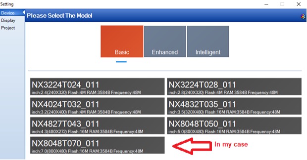
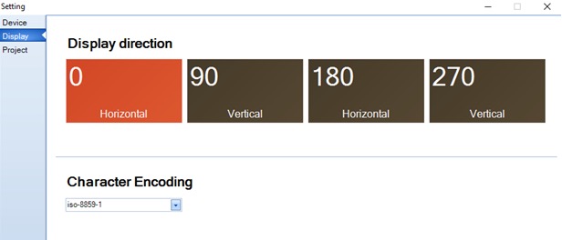
NX8048T070_011 is 7 inch 800×480. Once you are done, hit OK. Next, the orientation of the display is required to be selected. Select the orientation of the display. You can also select the character encoding. I prefer to work with default iso-8891-1. Hit Ok, and you are done with the display settings.
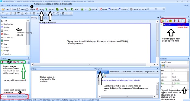
Main editor window
The main editor window comprises many small windows, each used to set different parameters/functions and configurations, overlooking the main window and its sub-windows.
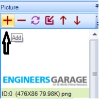
Let’s create two pages and jump from one to another. On the main page header, I want to display the EngineersGarage logo. So first, I need to import the logo into the editor. Click the add button navigate to the image, and press enter. The logo is imported and displayed in the window. Logo parameters size, height width, and format appear beneath it. The logo is assigned an ID-0. Every object in the editor is assigned an ID.
 To place this picture in the display pane double, click the picture object. A rectangular box will appear in the display pane. p0(picture0) is the object name.
 To display the EngineersGarage logo in the picture box, click the box and navigate to the attribute window. P0 attributes are listed in the window. Id is 1, scope is local (if global, then this object can be seen in other pages). The pic attribute is where we have to put the id of picture we want to display in the picture box. In our case, the logo id is 0, so put 0 and hit enter (You can also use the browse feature to select the pictures available in the picture window manually). The logo will appear in the picture box.
 Make sure your picture is not out of the display pane. Adjust it in a pane using a mouse.

Display text
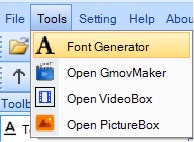
To display text first, we have to generate a font. Font generator application is part of the editor. Navigate to Tools>FontGenerator.
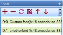
Generate font which you want to display on HMI. Give a valid name to each font, select height, and encoding, etc. If more than one font is part of the project, generate each one by one.
 I specified two fonts. You can view the fonts in the font window. Each font is assigned an ID and name.
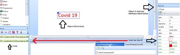
 To assign a text box, a particular font enters the font ID next to the font attribute. Attribute txt is where you input the text, which later appears in the text box. Pco attribute changes the color of the text. Each object and its attributes can be studied by using the help option from the editor.
 I created two pages few pictures and text boxes are present on each page. One button is placed on the main page. Pressing the button will take you to the next page.
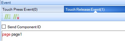
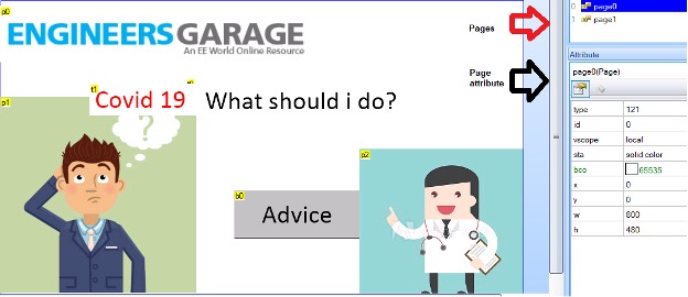 To switch between pages using a button, we must create an event. The event can be on button press or release. I specified on release. Put page page1 in the button release event. Commands can be studied using help from the editor menu.
 Now all you need to do is compile code and then start debugging.
Note: You don’t need any external hardware for this project—just a power supply for powering HMI.
Uploading the sketch to HMI
After successful debugging of the GUI application, it’s time to upload the sketch to HMI. The best solution is to upload it using a USB to TTL converter. Connect the serial converter to the USB port and its UART lines with HMI. From the text editor in the tools bar, select the COM port, set the baud rate to 9600, and hit upload. The sketch will start uploading, and it will take 3 to 6 minutes, depending on the application size.
Another method is to copy the .TFT file generated by the nextion editor in an SD card. Insert the card in the HMI sd-card slot and power up the HMI. GUI program will automatically be uploaded in the HMI. You can remove the sd-card when the upload is finished.
Let’s DIY it: Where to purchase parts?
Mouser: Nextion HMI display
Mouser: USB to UART
Mouser: Power supply
You may also like:


Filed Under: Electronic Projects

Questions related to this article?
👉Ask and discuss on EDAboard.com and Electro-Tech-Online.com forums.
Tell Us What You Think!!
You must be logged in to post a comment.