Low power design is a system using a collection of techniques and methodologies for the purpose of optimizing battery life and reducing the overall power dissipation of the system. To optimize the power there are many low power techniques that depend on the level of the design selected, ranging from semiconductor technology to the higher levels of abstraction. These abstraction levels are classified as a system, algorithm, architecture, circuit, and process levels which we will discuss further in the article and we will examine some of the information related to reducing power consumption on embedded systems. Then in a future article, we will discuss the features of the Microcontroller-based Low Power System and how you can use them to extend your battery life.
General terms
Before we go any further, we should know these terms:
Current. It is a measure of the amount of electrical charge transferred per unit of time through a closed circuit. The standard unit is amperes, which is defined as coulombs (a unit of charge) per second.
I=Q/t
Power. Electric power(P) is the rate at which work is done or energy is transformed into an electrical circuit.
P = VI
Where V is the potential difference in the circuit and I is the electric current through the electric circuit
Energy. Energy is the ability to do work. If the power is constant over the time interval then the energy can be expressed simply as
E = Pt
If power consumption is constant, energy consumption will be power * time during which power is consumed. Power consumption reduction will only save energy if the time required to complete the task does not increase.
Let us understand low power embedded systems by doing an experiment with LED brightness. Our aim here is to demonstrate how we can drive load on low power using an MCU.
Setup
Here we have used an Arduino to control the brightness of the LED. Arduino provides PWM (Pulse Width Modulation) that can periodically output HIGH and LOW. The PWM function, periodically switching between HIGH and LOW at a specified rate, can be used to adjust the LED brightness.
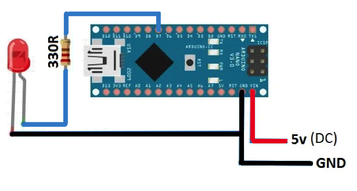
Fig: 1 Experiment Setup
Code explained
To create a PWM signal, we use the function analogWrite(x, y), where x is the digital pin and y is a value for the “duty cycle”, between “0 and 255” where 0 indicates 0% duty cycle and 255 indicates 100% duty cycle which means when the PWM ratio reaches 255, it is decreased until it reaches 0 to darken the LED gradually.
The duty cycle is the ratio of time a load or circuit is ON compared to the time the load or circuit is OFF. A 60% duty cycle is a signal that is ON 60% of the time and OFF 40%.
Test 1
When the PWM ratio is 10 and Duty Cycle is 4%.
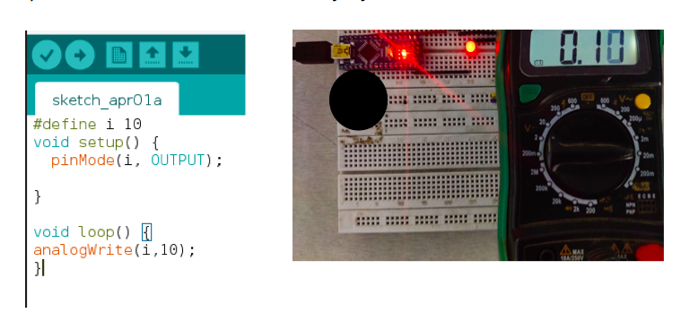
Fig: 2 Experiment with Low LED brightness.
The low brightness of the LED (10 %) uses less drive current which means less power is consumed. And in 100mA of battery with a load of 0.1mA, the run time will be 1000 hours.
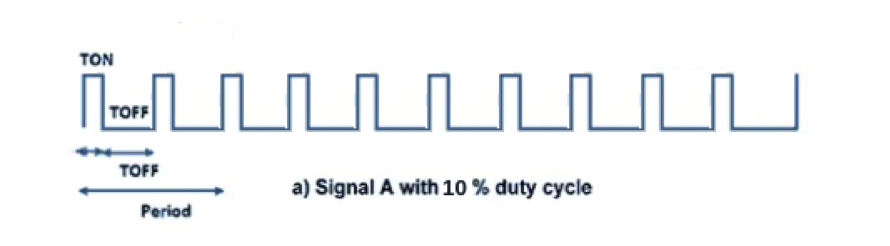
Figure 3. Signal A with 10% duty cycle
Test 2
When the PWM ratio is 150 and duty cycle is 58%.
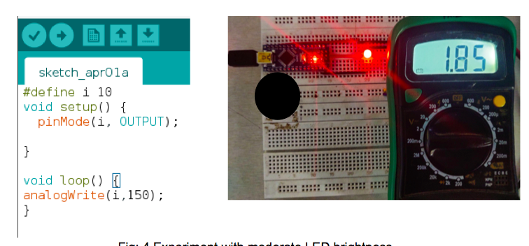
Fig: 4 Experiment with moderate LED brightness.
The half brightness of the LED (58 %) uses the half drive current which means half power is consumed. In 100mA of battery with a load of 1.85mA, the run time will be 54 hours.

Fig.5: Signal A with 58% duty cycle
Test 3
When the PWM ratio is 255 and duty cycle is 100%.

Fig: 6 Experiment with full LED brightness.
The full brightness of the LED (100 %) uses the full drive current which means more power is consumed. In 100mA of battery with a load of 3.16mA, the run time will be 31 hours.

Fig. 7: Signal A with 100% duty cycle
The current is proportional to the LED brightness. So, the current is less if the LED’s brightness is less which implies that low power consumption will equal low energy consumption.
Why do we need low power design?
Embedded systems need to be energy efficient during operation to ensure a long battery lifetime, reduce utility power consumption, and prevent excess heat generation. The longer battery life of a product can also lead to lower maintenance costs, as costly visits to replace batteries occurs less frequently. Additionally, portable devices such as cellular phones, gaming consoles, and battery-powered electronic systems demand microelectronic circuits designed with ultra-low power dissipation. For example, metering solutions like Automatic Meter Reading(AMR) require longer battery life and portability as they need to be fixed on each and every meter. They should run about 8- 10 years after the installation.
Levels of power optimization
The low power design of any system is a combination of optimized manufacturer, software, and hardware. In these combinations power reduction can be implemented at different levels of design abstraction: system, architecture, algorithms, circuit, and the process level. The most efficient design decisions derive from choosing and optimizing architectures and algorithms at these levels. Let’s discuss these Levels briefly on which energy reduction can be incorporated:
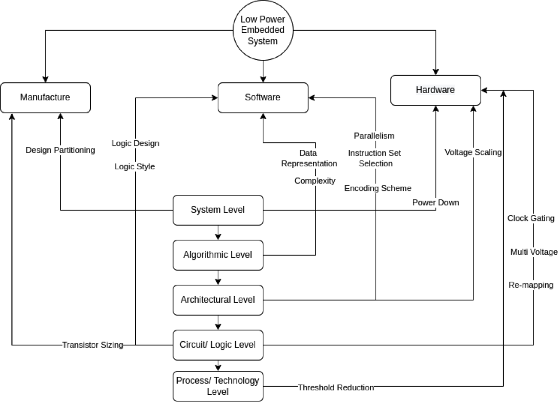
Fig. 8: Design Flow Levels
- System Level: This level includes the power optimization techniques which can be done at the time of manufacturing of ICs and also at the hardware level. For example, design partitioning is the practice of dividing a system on chip (SoC) into small blocks which is done on the manufacturer’s side. This allows users to efficiently manage semiconductor designs as a related set of functional blocks. Semiconductor designs are most efficiently managed as related sets of functional blocks.
- Algorithmic Level: In this technique, the number of operations that require larger power is reduced which is basically part of the Software This approach reduces the number of operations and hence reduces the number of hardware resources. For Example, Most DSP(digital signal processing) algorithms involve several multiplication operations. Multiplication is the most power-consuming operation in such algorithms and can be replaced by shift-add (This method adds the multiplicand X to itself Y times, where Y denotes the multiplier) operations to reduce power.
- Architectural Level: Architecture level measures include smart power management of various system blocks, utilization of pipelining and parallelism, design of bus structures, and voltage scaling. At this level, the power reduction can be done on both the hardware and software side. For example, energy consumption in CMOS circuitry is proportional to capacitance. While designing the PCB we can minimize the bus length by optimal module placement which will reduce the capacitance.
- Logic/Circuit Design Level: This level includes the power optimization techniques which can be done at the time of manufacturing of ICs, hardware as well as software side. For example, Transistor Sizing is the process of reducing or increasing the channel width of the transistor at the time of manufacturing. The smaller your transistors, the more transistors can fit on a chip, and the faster and more efficient processor can be. Another example is to use a custom design at the hardware side in which components in a circuit used are more static than dynamic.
- Process Level: This level includes the power optimization techniques which can be done only on the hardware side of the system. For example, multi-supply voltages are being used in different functional blocks of the core for saving power. Another example, reducing a supply voltage from 5.0 to 3.3 volts (a 44% reduction) reduces power consumption by about 56%.
**We will discuss these in detail in a future article.
Power modeling
Power modeling is a technique or procedure to study the power generated, lost, and distributed in a system. It helps in recording past data of power flow and preparing future plans and system design. In power modeling the Total Power Dissipation (PT) can broadly be divided into the following:
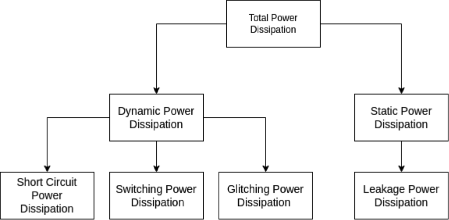
Fig. 9: Power Dissipation Model
Static Power Dissipation (PS): Power consumed during a standby mode. (When the microcontroller is in sleep mode but LDO(Low Drop Out) is active and consumes power)
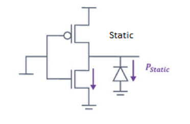
Fig. 10: Static Power Dissipation
Dynamic Power Dissipation (PD): Power dissipation during a signal switching at the cell input during and discharging of the capacitances in the circuit. Switched capacitance is the primary source of dynamic power consumption and arises from the charging and discharging of capacitors at the outputs of circuits.

Fig. 11: Dynamic Power Dissipation
Short Circuit Power Dissipation (PSC): It is the secondary source of dynamic power consumption where power is dissipated by an instantaneous short-circuit connection between the supply voltage and the ground at the time the gate switches state which can cause dissipation of more than 20% of the total power.
PT = PS + PD + PSC
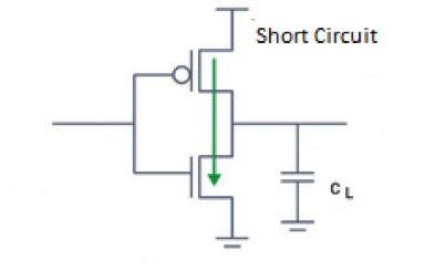
Fig. 12: Short Circuit Power Dissipation
Low power embedded system applications
These include the following:
- Low maintenance Devices
- Digital wristwatches
- Fitness tracker
- Interactive Kiosks
- Beacons
- Cameras
- Mobile Phones
- Unattended Internet-of-Things (IoT) systems
You may also like:


Filed Under: Arduino, Power, Tech Articles, Tutorials, What Is

Questions related to this article?
👉Ask and discuss on EDAboard.com and Electro-Tech-Online.com forums.
Tell Us What You Think!!
You must be logged in to post a comment.