These smart clocks, powered by the ESP8266 D1 Mini, offer more than just timekeeping. In addition to displaying the current time, they measure temperature and humidity, making them versatile tools for monitoring environmental conditions.
Equipped with a DHT22 sensor, these clocks provide accurate air temperature and humidity readings, displayed alongside the time on a 1.8-inch TFT LCD screen. Below we’ll cover how to design your own smart clock!

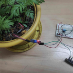
Figure 1. The prototype.
Thanks to the ESP8266’s network capabilities, this smart clock retrieves the date, time, temperature, and humidity, providing essential data all in one place. These features make it practical and easy to use.
Components
- ESP8266 D1 mini board
- DHT22 sensor
- A 1.8-inch TFT LCD screen (ST7735 chipset)
- A 560-ohm resistor
Note: If your ESP8266 board lacks a BOOT button, you may need to connect the GPIO0 to the GND by using the 560-ohm resistor (unless the code uploads automatically).

Figure 2. The components.
How it works
The ESP8266 D1 Mini connects to the network, requesting the time and date from an NTP server. The server then sends this data to the ESP8266 D1 Mini.

Figure 3. The working principle.
How to install and set-up Arduino IDE
- Download and install Arduino IDE — ideally Version 1.8.19 (the newer versions may have bugs).
- After installing, go to “File” > “Preferences.”
- In the “Preferences” window, find “Additional Boards Manager URLs” and paste this link: http://arduino.esp8266.com/stable/package_esp8266com_index.json
- Next, go to “Tools” > “Board” > “Boards Manager.”
- In the “Boards Manager” window, type “esp8266” in the search field.
- Find the ESP826 boards package and click “Install.”

Figure 4. Screenshots for reference.
How to download the CH340 driver
For Windows:
- Download the CH340 driver from this link:
http://wiki.amperka.ru/_media/articles:driver-ch340:ch340ser-wimdows.zip - Extract the downloaded .zip file.
- Open the extracted folder.
- Run the .exe file and follow the installation prompts.
For Mac:
- Download the CH340 driver from this link:
http://wiki.amperka.ru/_media/articles:driver-ch340:ch340ser-mac.zip - Extract the downloaded .zip file.
- Open the extracted folder.
- Install the driver as per the instructions provided.

Figure 5. Installing the CH340 driver.
How to install the libraries
- Go to “Sketch” > “Include Library” > “Manage Libraries.”
- Search for each library one by one and download them:
- DHT
- SPI
- ESP8266WiFi
- NTPClient
- Adafruit_ST7735
- Adafruit_GFX
- WiFiUdp
How to download the firmware
- Go to the Smart Clocks GitHub repository: https://github.com/NickProgrammerOffical/Smart-Clocks
- Download the “Smart-Clocks.zip” folder.
- Extract the downloaded folder.
- Open the “Firmware.ino” file using the Arduino IDE.

Figure 6. Screenshot for reference.
Setting the time zone and format
- Find your city’s GMT offset for its proper time zone.
- Adjust the “int GMT” value in the code to match your city’s GMT offset.
- Choose your time display format:
- For 24-hour format, set “display_time” to “24/H”.
- For AM/PM format, set “display_time” to “AM/PM”.\\

Figure 7. Setting the time.
The assembly
Ensure that the connection between the DHT22 sensor and resistors is secure and done correctly.
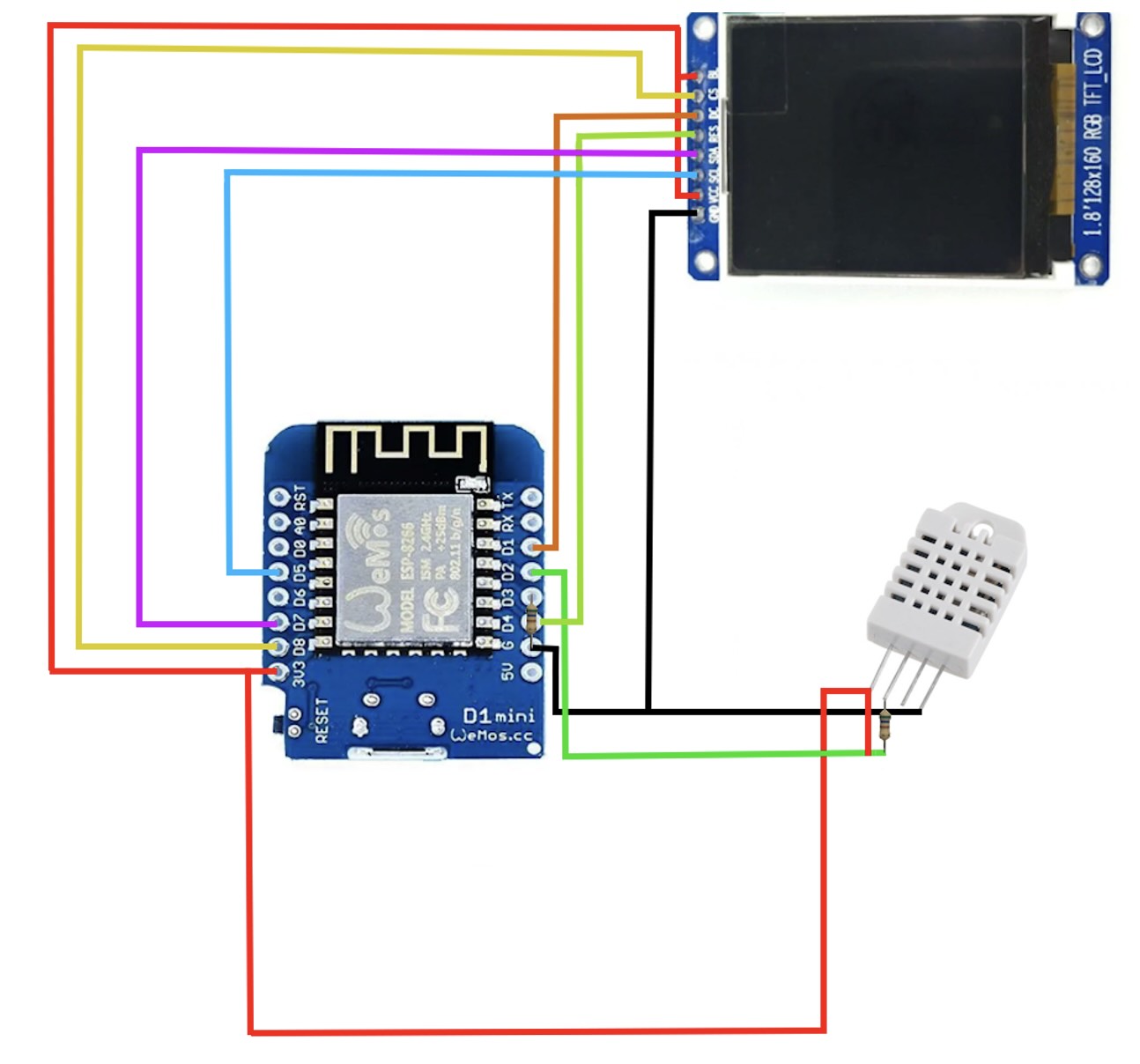
Figure 8. The circuit connections.
Updating the firmware
- Update the WIFI_SSID and WIFI_PASS values with your Wi-Fi network’s SSID and password.
- Select the board and port for uploading the firmware.
- Go to “Tools” > “Board” > “ESP8266 Boards” > “LOLIN(WEMOS) D1 mini.”
- Connect GPIO0 to the GND pin using a 560 ohm resistor.
- Go to “Tools” > “Port” and select your port.
- Click the upload button in the top left corner to upload the firmware.

Figure 9. A working prototype.
Using the smart clock
To use the smart clock, you’ll need a hotspot or Wi-Fi router. The ESP8266 board will automatically connect to the network and retrieve the date and time.
Final Code
You may also like:


Filed Under: Circuit Design
Log in to leave a comment:
Lost your password?
Don't have an account? Register here