Engineers Garage

  • Projects and Tutorials
    • Electronic Projects
      • 8051
      • Arduino
      • ARM
      • AVR
      • PIC
      • Raspberry pi
      • STM32
    • Tutorials
    • Circuit Design
    • Project Videos
    • Components
  • Articles
    • Tech Articles
    • Insight
    • Invention Stories
    • How to
    • What Is
  • News
    • Electronic Products News
    • DIY Reviews
    • Guest Post
  • Forums
    • EDABoard.com
    • Electro-Tech-Online
    • EG Forum Archive
  • Digi-Key Store
    • Cables, Wires
    • Connectors, Interconnect
    • Discrete
    • Electromechanical
    • Embedded Computers
    • Enclosures, Hardware, Office
    • Integrated Circuits (ICs)
    • Isolators
    • LED/Optoelectronics
    • Passive
    • Power, Circuit Protection
    • Programmers
    • RF, Wireless
    • Semiconductors
    • Sensors, Transducers
    • Test Products
    • Tools
  • EE Resources
    • DesignFast
    • LEAP Awards
    • Oscilloscope Product Finder
    • White Papers
    • Webinars
  • EE Learning Center
    • Design Guides
      • WiFi & the IOT Design Guide
      • Microcontrollers Design Guide
      • State of the Art Inductors Design Guide
  • Women in Engineering

How to build an IR remote-operated RGB LED strip using Arduino

By Ashutosh Bhatt

In the previous article from this series, we learned how to generate different colors in an RGB LED strip when using Arduino. We covered the basics in terms of how an RGB LED strip works, the types available, and how it can generate various colors. 

In this article, we’ll add to that knowledge base. You might already be familiar with some of the LED strips available on the market, including ones with a small remote. This IR remote operates the strip and is used to turn it on or off, change the colors, and increase or decrease the brightness, etc.

The idea for this project is similar. We’re going to build IR remote-operated RGB LED strip using Arduino. What’s interesting (and convenient) is that you can use any IR remote to operate it — including an STB or TV remote, or any other IR remote. 

So, let’s get started. First, we’ll review the circuit diagram and how it operates, followed by the program.

Circuit diagram

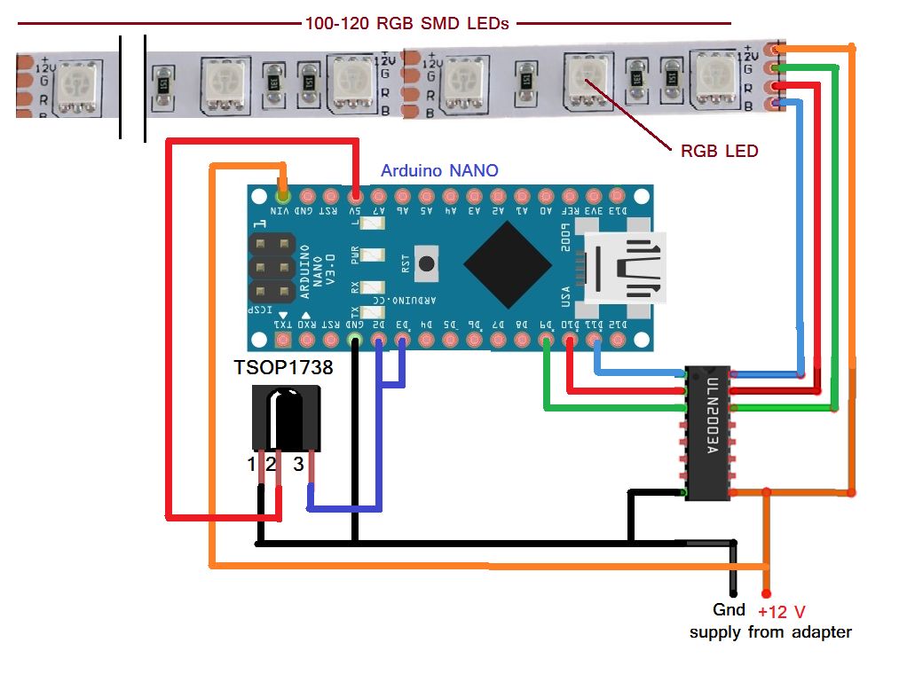
This circuit is built using only four components:

  • The TSPO1738 is an IR receiver (sensor) that receives remote signals (from any IR remote). It has these interfacing pins: Vcc, GND, and output. The Vcc pin receives 5V from the Arduino board. The ground pin must be connected to the common ground. And, the output pin should be connected with Arduino’s pins D2 and D3.
  • The ULN2003A is a current-driver chip with built-in Darlington pairs (7) that are used to provide current to the LED strip. It receives the same 12V supply that’s given to both the RGB strip and Arduino. Arduino analog outputs D9, D10, and D11 are connected to three of the chip’s inputs. Its corresponding outputs are connected with the strip’s R, G, and B inputs.
  • The Arduino board, ULN2003A chip, and strip all are given 12 V supply from an adapter ([email protected]).

Circuit operation

  • It’s important to first read and decode the codes from the IR remote that you plan to use. To do so, simply connect TSOP1738 with the Arduino board, as shown.
  • Next, download the library called, “IRremote” from GitHub. Copy the library into the root directory (folder) or to Arduino (C:\arduino-1.6.7\libraries). Then, you should easily be able to access the library from the Arduino IDE software as: sketch menu -> include library -> IRRemote 
  • Upload the program given here into Arduino.
  • Allow Arduino to connect to your laptop/PC through a USB cable.
  • Run the program and start the serial monitor in Arduino IDE.
  • Now, press any button from the remote that you’d like to use. You’ll see some code pop up (such as… 4 – 5 – 6 – 8 – 10 digits). Note down these codes for their respective buttons. They will also be used for controlling the strip.
  • These codes will also be used in the main program to perform different operations, such as changing the color or brightness, etc. 

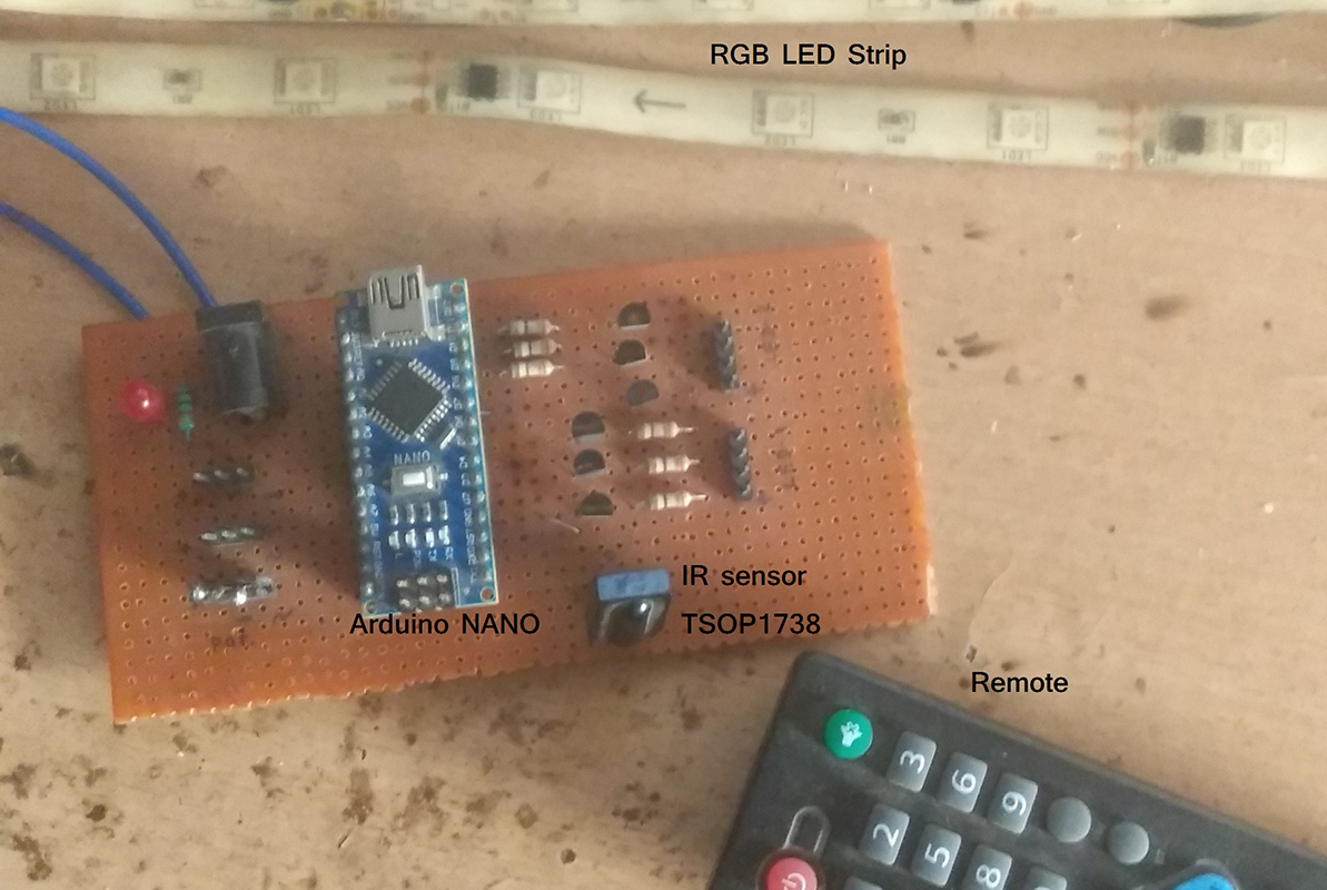
The IR remote-operated RGB LED strip.

Next, let’s review how the complete circuit works…

  • The IR sensor, TSOP1738, receives code from the remote and passes this message onto Arduino.
  • Arduino first decodes this message and compares it with the programmed code. 
  • If a match is found, Arduino will provide the PWM outputs on D9, D10, and D11 to generate different colors on the LED strip. For example, when any number key is pressed from the remote (1, 2, 3, etc.), Arduino will generate RED, GREEN, BLUE, etc .— the pre-programmed colors.
  • If the ‘0’ key is pressed on the remote, Arduino will generate a continuous multi-color effect. To stop this effect, you’ll need to reset the Arduino microcontroller.

Software program
Program 1: To decode the IR remote codes

Program 2: main program


Filed Under: Electronic Projects
Tagged With: Arduino
 

Questions related to this article?
👉Ask and discuss on EDAboard.com and Electro-Tech-Online.com forums.


Tell Us What You Think!! Cancel reply

You must be logged in to post a comment.

HAVE A QUESTION?

Have a technical question about an article or other engineering questions? Check out our engineering forums EDABoard.com and Electro-Tech-Online.com where you can get those questions asked and answered by your peers!


Featured Tutorials

  • PS2 Keyboard To Store Text In SD Card Using Arduino Circuit Setup On Breadboard
    How To Use PS2 Keyboard To Store Text In SD Card Using Arduino- (Part 42/49)
  • Wireless Path Tracking System Using Mouse, XBee And Arduino Circuit Setup On Breadboard
    How To Make A Wireless Path Tracking System Using Mouse, XBee And Arduino- (Part 43/49)
  • How to Make a Wireless Keyboard Using Xbee with Arduino- (Part 44/49)
  • Making Phone Call From GSM Module Using Arduino Circuit Setup On Breadboard
    How to Make Phonecall From GSM Module Using Arduino- (Part 45/49)
  • How to Make a Call using Keyboard, GSM Module and Arduino
    How To Make A Call Using Keyboard, GSM Module And Arduino- (Part 46/49)
  • Receiving SMS Using GSM Module With Arduino Prototype
    How to Receive SMS Using GSM Module with Arduino- (Part 47/49)

Stay Up To Date

Newsletter Signup

Sign up and receive our weekly newsletter for latest Tech articles, Electronics Projects, Tutorial series and other insightful tech content.

EE Training Center Classrooms

EE Classrooms

Recent Articles

  • Renesas and Cyberon to deliver integrated voice-user interface solutions
  • STMicroelectronics releases Bluetooth SoC with location tracking
  • Infineon launches AI/ML-based sensor fusion alarm system
  • Renesas delivers intelligent sensor solutions for IoT applications
  • Microchip Technology releases AVR-IoT Cellular Mini Development Board

Most Popular

5G 555 timer circuit 8051 ai Arduino atmega16 automotive avr bluetooth dc motor display Electronic Part Electronic Parts Fujitsu ic infineontechnologies integratedcircuit Intel IoT ir lcd led maximintegratedproducts microchip microchiptechnology Microchip Technology microcontroller microcontrollers mosfet motor powermanagement Raspberry Pi remote renesaselectronics renesaselectronicscorporation Research samsung semiconductor sensor software STMicroelectronics switch Technology vishayintertechnology wireless

RSS EDABOARD.com Discussions

  • Holding an SMPS Former to PCB with fishing line?
  • D Flip Flop frequency divider
  • Limits of duty cycle for ICM7555 IC?
  • 12V 5A needed
  • Characterization values of a MOSFET in PDK

RSS Electro-Tech-Online.com Discussions

  • writing totals in Eprom
  • ICM7555 IC duty cycle limit at high frequency?
  • undefined reference header file in proteus
  • How to test phone socket?
  • intro to PI
Engineers Garage
  • Analog IC TIps
  • Connector Tips
  • DesignFast
  • EDABoard Forums
  • EE World Online
  • Electro-Tech-Online Forums
  • Microcontroller Tips
  • Power Electronic Tips
  • Sensor Tips
  • Test and Measurement Tips
  • 5G Technology World
  • About Us
  • Contact Us
  • Advertise

Copyright © 2022 WTWH Media LLC. All Rights Reserved. The material on this site may not be reproduced, distributed, transmitted, cached or otherwise used, except with the prior written permission of WTWH Media
Privacy Policy | Advertising | About Us

Search Engineers Garage

  • Projects and Tutorials
    • Electronic Projects
      • 8051
      • Arduino
      • ARM
      • AVR
      • PIC
      • Raspberry pi
      • STM32
    • Tutorials
    • Circuit Design
    • Project Videos
    • Components
  • Articles
    • Tech Articles
    • Insight
    • Invention Stories
    • How to
    • What Is
  • News
    • Electronic Products News
    • DIY Reviews
    • Guest Post
  • Forums
    • EDABoard.com
    • Electro-Tech-Online
    • EG Forum Archive
  • Digi-Key Store
    • Cables, Wires
    • Connectors, Interconnect
    • Discrete
    • Electromechanical
    • Embedded Computers
    • Enclosures, Hardware, Office
    • Integrated Circuits (ICs)
    • Isolators
    • LED/Optoelectronics
    • Passive
    • Power, Circuit Protection
    • Programmers
    • RF, Wireless
    • Semiconductors
    • Sensors, Transducers
    • Test Products
    • Tools
  • EE Resources
    • DesignFast
    • LEAP Awards
    • Oscilloscope Product Finder
    • White Papers
    • Webinars
  • EE Learning Center
    • Design Guides
      • WiFi & the IOT Design Guide
      • Microcontrollers Design Guide
      • State of the Art Inductors Design Guide
  • Women in Engineering