ADC is an electronic device which converts analog signals into its corresponding digital signal. This article demonstrates the principle, operation and interfacing of 8-bit serial ADC0831 with 8051 microcontroller (AT89C51).
ADC0831 is an 8 pin IC with 8-bit serial data output (for more detail about ADC0831 refer to Interfacing ADC0831 with ATmega16). To receive the output from ADC high to low pulse is given at CS (chip select) pin of ADC form controller. ADC requires delay of two clock pulses before starting data conversion. At the second clock cycle, ADC sends a ‘0’ bit to the controller which indicates that the upcoming bits are the data bits.
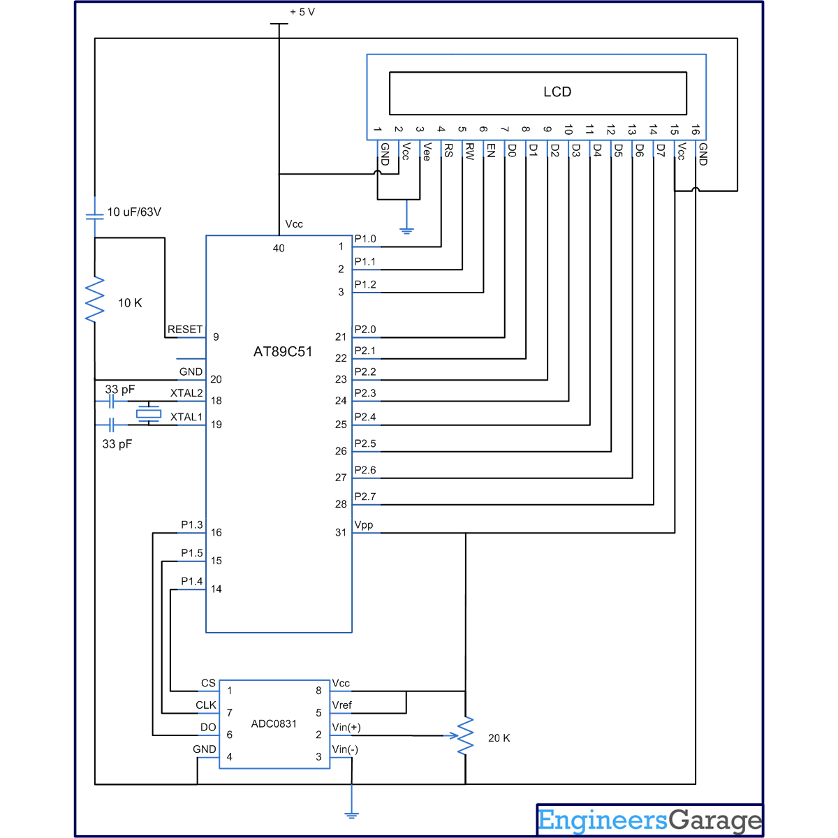
ADC needs eight clock pulses to send 8-bit digital output. This digital data is received bit by bit and stored in a variable. The data is converted to its corresponding ASCII value and sent to LCD for display. The connections of LCD with microcontroller are shown in circuit diagram. The analog signals are generated by at a variable resistance (preset) which is connected to input pin of ADC0831.
Algorithm
1. Initialize LCD.
2. Send a high to low pulse to CS pin to initialize conversion.
3. Send two clock pulses.
4. Receive the data bits by one by one and store it in a variable.
5. Display its corresponding decimal value on LCD.
Project Source Code
###
// Program to Interface ADC0831 with 8051 Microcontroller#include<reg51.h>#include<intrins.h>sfr lcd_data_pin=0xA0;//p2 portsbit rs=P1^0;sbit rw=P1^1;sbit en=P1^2;sbit DO=P1^3;sbit CS=P1^4;sbit clk=P1^5;unsigned char read,value,lcd;void delay(unsigned int count){int i,j;for(i=0;i<count;i++)for(j=0;j<1275;j++);}void lcd_command(unsigned char comm){lcd_data_pin=comm;en=1;rs=0;rw=0;delay(1);en=0;}void lcd_data(unsigned char disp){lcd_data_pin=disp;en=1;rs=1;rw=0;delay(1);en=0;}lcd_dataa(unsigned char *disp){int x;for(x=0;disp[x]!=0;x++){lcd_data(disp[x]);}}void lcd_ini(){lcd_command(0x38); // for using 8-bit 2 row LCDdelay(5);lcd_command(0x0F); // for display on cursor blinkingdelay(5);lcd_command(0x0C);delay(5);lcd_command(0x80);delay(5);}void lcd_display(unsigned char val){unsigned char flg=0;lcd_command(0xC7);if(val==0)lcd_data('0');while(val>0){lcd=val%10;val=val/10;lcd_command(0xC7-flg);lcd_data(lcd+'0');flg++;}if(flg==1){lcd_command(0xC6);lcd_data(' ');lcd_command(0xC5);lcd_data(' ');}if(flg==2){lcd_command(0xC5);lcd_data(' ');}}unsigned char read_byte(){unsigned char i;read=0;for(i=0;i<8;i++){read=read<<1; //shift variable by one bitclk=1;_nop_();_nop_();if(DO==1) // if receive bit is one{read++; // increase the value of read by one else do nothig}clk=0;}return read; // return digital data stored in "read" variable}void adc(){DO=1;CS=1;_nop_();_nop_();CS=0;clk=1;_nop_();_nop_();clk=0;clk=1;_nop_();_nop_();clk=0;value=read_byte();lcd_display(value);}void main(){lcd_ini();lcd_dataa("ADC OUTPUT: ");while(1){value=read_byte();adc();}}###
Circuit Diagrams
Project Components
Project Video
Filed Under: 8051 Microcontroller.
Filed Under: 8051 Microcontroller.


Questions related to this article?
👉Ask and discuss on Electro-Tech-Online.com and EDAboard.com forums.
Tell Us What You Think!!
You must be logged in to post a comment.