Introduction:
Rain detector circuit is the device which will really work as you wish what you want to do. It is a device which will generate the signal when the rain comes. The frequency will be more when the rain is heavier and the frequency is very less when the rain will be low. It all means that the frequency will depend upon the rain. We always should focus upon the signal making. Don’t focus on the rest of the part which we have to make it. When we get the signal now we can do anything we want to do.
We will make a single wire circuit so that the circuit is easy and every reader can read it. Double wired is quiet complicated and the circuit which is made has to be with a IC’s so I will prefer today to show you with single cable and for complicated circuit you may go to article how to make a rain detector with IC’s.
1st experiment:
As you know that not a single machine is made with having all facilities in first attempt so here it go.
This is the easiest circuit that you have ever seen. In the practical of school, this is done in 5th or 6th class. It is very easy to make and only few cheapest thing is required.
Aim: To make rain detector.
Material required:
LED, connecting wire, battery and a zigzag switch like in calculator.
Procedure:
1. Connect everything as you can. I hope that you can glow the led by connecting the wire. And you will not see in the pitcher for help you can see this picture.
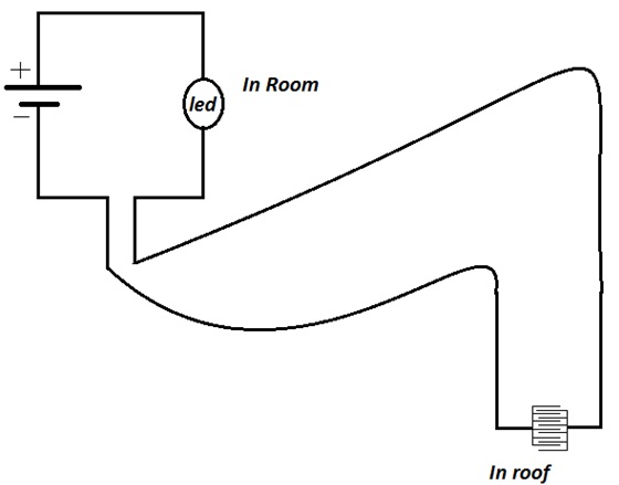
Fig. 1: Circuit Diagram of LED Indicator
2. Prepare rain detector probe. For that only connect the wire on the two end of the switch.
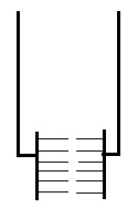
Fig. 2: Circuit Diagram of LED Indicator modified for Rain Detection
3. Connect wire of that length so that the detector reaches your roof.
4. Cut the wire of the led circuit from anywhere.
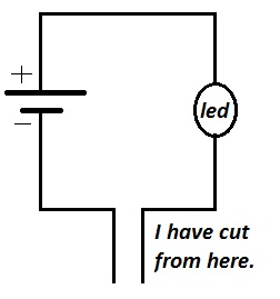
Fig. 3: Circuit Diagram of Rain Detector
5. Connect the detector in the terminals of the led circuit.

Fig. 4: Circuit Diagram of LED Indicator
6. Now when the rain will come or the detector pad become wet by any source then the circuit will glow
We have made a circuit that will work according to the rain. But there are lot of disadvantage on this circuit.
Advantages:
1. It is very cheap.
2. The battery last very much.
3. Not risky.
4. No harmful effect.
5. The circuit can be made by everyone.
Disadvantages:
1. It doesn’t tell about the speed of the rain which is fallen on the roof.
2. It will send signal or the led will be glowing until the detector becomes wet.
3. It something is over that then the detector will not work until it gets wet.
4. There are so many problem that you will face when you will make this circuit.
To minimise the disadvantageous we have made some changes that will be in experiment 2.
Enhanced Circuit
2nd experiment:
This is the modified experiment that in this the only the change is in the detective plate.
Aim: To make good rain detector.
Material required:
LED, connecting wire, grills and battery.
Procedure:
7. Connect everything as you can. I hope that you can glow the led by connecting the wire. And you will not see in the pitcher for help you can see this picture.
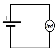
Fig. 5: Image of a Rain Probe
8. Prepare rain detector probe. For that only connect the wire on the two end of the switch.

Fig. 6: Circuit Diagram of LED Indicator modified for Rain Detection
9. Connect wire of that length so that the detector reaches your roof.
10. Cut the wire of the led circuit from anywhere.

Fig. 7: Circuit Diagram of Rain Detector
11. Connect the detector in the terminals of the led circuit.
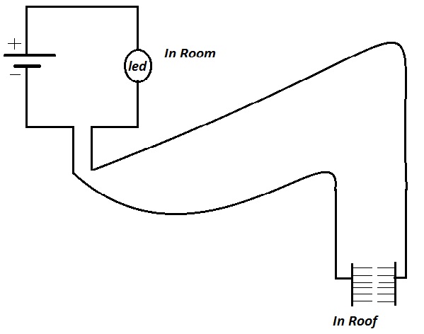
Fig. 8: Prototype of Rain Detector
12. Now when the rain will come or the detector pad become wet by any source then the circuit will glow
We have made a circuit that will work according to the rain. But there are lot of disadvantage on this circuit.
Advantage:
1. It is very cheap.
2. The battery last very much.
3. Not risky.
4. No harmful effect.
5. The circuit can be made by everyone.
6. It doesn’t tell about the speed of the rain which is fallen on the roof.
Disadvantages:
1. It doesn’t tell how much does the rain have at a given time.
2. It doesn’t tell the rain timing.
3. It doesn’t tell many more details require.
Creating signals:
Now for signal only thing you have to do is add transistor as shown in diagram.
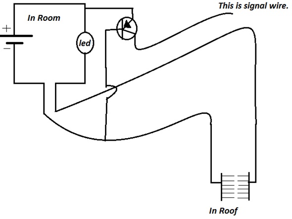
Fig. 9: Complete Prototype of Electronic Rain Detector
Filed Under: Electronic Projects


Questions related to this article?
👉Ask and discuss on Electro-Tech-Online.com and EDAboard.com forums.
Tell Us What You Think!!
You must be logged in to post a comment.