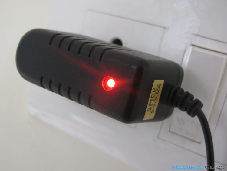
Mobile phones are very common these days and so mobile chargers too. Most of us use it in daily life. In fact they are used to charge the batteries inside the mobiles by providing them a low level DC voltage and current. There may be different types of chargers used to charge different mobile phones but the key functioning of those all are almost same.

Fig. 1: Image of a Mobile Charger
The above image shows a commonly used mobile charger.
PCB with Components

Fig. 2: PCB Circuitry of Mobile Charger
On opening the outer screws, we can see the PCB having majority of the components as shown in the image above.

Fig. 3: Four Diodes Imbibed in Mobile Charger PCB
Four diodes shown in the upper image are arranged to make a full wave rectifier circuit. The working of the rectifier is explained later in the article.
Other Components

Fig. 4: PCB Circuitry Components—Capacitors, Transistors, Diodes, and Resistors
The above image gives a clear look to the components that are used in the circuitry – capacitors, transistors, diodes and resistors.

Fig. 5: Pulse Transformer of Mobile Charger
A pulse transformer shown in the above image is a special purpose transformer.
Working

Fig. 6: LED of Mobile Charger
When charger is connected with the AC supply, the LED starts glowing to indicate the proper operation of the charger.
Working
Latest mobile chargers are kind of power supply units that use the Switched Mode Power Supply (SMPS) technology. To understand the working phenomenon of a mobile charger, we need to understand the concept of Power Supply Unit (PSU). PSU is a device that transfers electrical energy from one end to another by changing its fundamental characteristics according to the requirements. Example of a PSU is an application that converts AC mains voltage to regulated DC voltage. PSUs can be of two types depending on the mode of operation – Linier and Switching.
In these switching mode chargers, energy transfer is done by continuously switching electrical components (inductor, capacitor, etc) on and off. We can control the output voltage/current by varying the duty cycle, frequency or the corresponding phase. Using the SMPS technology makes the chargers smaller and lighter by elimination of low frequency transformers. It also presents a greater efficiency than the conventional methods which uses bulky transformers.
The AC supply first enters through the line filters in the charger. Line filters are the kind of electronic filters that are placed between an electronic device and an external line to alter/attenuate the electromagnetic interference effect. Now filtered signal are made to pass through the full wave bridge rectifier circuit. Rectifier converts the AC voltage to DC.
Output DC voltage from rectifier circuit passes through the PFC (Power Factor Correction) circuit which operates power circuits at their maximum efficiency. Further the voltage signal is transferred to the pulse transformer that is a special type of transformer optimized to produce rectangular electrical pulses.
Pulse transformers are categorized into two categories – power and signal transformers. The one used here is a power transformer. It reduces the voltage level of the input power and gives a low voltage power that is exactly required to charge the battery.
Filed Under: Insight


Questions related to this article?
👉Ask and discuss on EDAboard.com and Electro-Tech-Online.com forums.
Tell Us What You Think!!
You must be logged in to post a comment.