Engineers Garage

  • Projects and Tutorials
    • Circuit Design
    • Electronic Projects
      • 8051
      • Arduino
      • ARM
      • AVR
      • PIC
      • Raspberry pi
      • STM32
    • Tutorials
    • Components
  • Articles
    • Tech Articles
    • Insight
    • Invention Stories
    • How to
    • What Is
  • News
    • EE Design News
    • DIY Reviews
    • Guest Post
    • Sponsored Content
  • Forums
    • EDABoard.com
    • Electro-Tech-Online
    • EG Forum Archive
  • Digi-Key Store
    • Cables, Wires
    • Connectors, Interconnect
    • Discrete
    • Electromechanical
    • Embedded Computers
    • Enclosures, Hardware, Office
    • Integrated Circuits (ICs)
    • Isolators
    • LED/Optoelectronics
    • Passive
    • Power, Circuit Protection
    • Programmers
    • RF, Wireless
    • Semiconductors
    • Sensors, Transducers
    • Test Products
    • Tools
  • EE Resources
    • DesignFast
    • LEAP Awards
    • Oscilloscope Product Finder
    • Video
    • White Papers
    • Webinars
  • EE Learning Center
  • Women in Engineering

Insight – How Banana Jack/Connector Works

November 26, 2012 By Ashutosh Bhatt


hand blender

Fig. 1: Image of Banana Jack/Connector

Banana connectors are a popular species of electrical connectors which find major use in connecting power amplifiers, speakers, woofers etc. in audio systems. Designed for high power applications, these connectors are known to work at an average of 1000volts and 15amperes. In any audio set up, the connectors are color coded into red and black where red connector holds the live wire while the black one serves as a reference (ground). Except the color coding, there is no structural difference between the connectors.

This Insight will give you a sneak-peek inside the assembly of such a connector, along with its external and internal details. 

Outer Structure
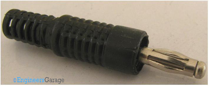
Outer Structure and Mechanics of Banana Connector

Fig. 2: Outer Structure and Mechanics of Banana Connector

Outer Structure: Image 02 pictures a conventional male banana connector. An assembly of metal contact and a plastic sleeve, the assembly is both durable and compact. The plastic sleeve is made from Nylon while the metal contacts are made from copper and plated with nickel.
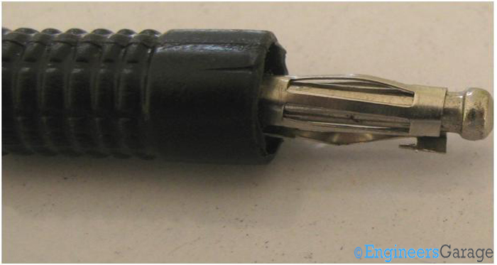
Spring Plug Mechanism of Connector

Fig. 3: Spring Plug Mechanism of Connector

A plug spring structure is placed on the connector. This spring enables a good link with the female counterpart.

Male & Female Connectors

(Left image) Input Port (Right image) Male Connector

Fig. 4: (Left image) Input Port (Right image) Male Connector

Different Banana Connectors: Male and female connectors are shown in Image03 and Image04, respectively. The female appears to be a simple input port. When male connector is inserted, the plug springs get compressed the moment the connector is inserted. After the insertion is complete, the spring jumps back to its rest position and a tight link is established.

Connector Linking Mechanism

Fig. 5: Connector Linking Mechanism

Link between male and female connectors: Image 05 details with the manner in which the connectors mate. Even when kept in an oblique position, the link is as good as it is in the earlier position.

 Engaging Force and Dissembled Connector
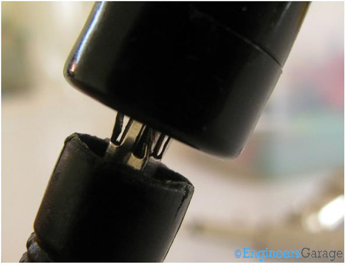
Image Showing Strong Engaging Force of Connectors

Fig. 6: Image Showing Strong Engaging Force of Connectors

Tight Connection: The force required to disengage the connectors is more when compared to the force required in engaging them. A connection like this is not only resistant to mechanical stresses but also maintains the signal quality for high power systems.
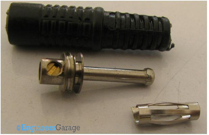
Dissembled Parts of Connector showing Mechanism of Banana Jack Connector

Fig. 7: Dissembled Parts of Connector showing Mechanism of Banana Jack Connector

Dissembled Connector: The assembly is uncomplicated and the metal contact can be easily plucked out of the plastic sleeve with hands. However, once opened, the contact pin region reveals a screw through which the wire connects. It also has rings through which it gets attached to the plastic part of the connector.

Connecting Screw
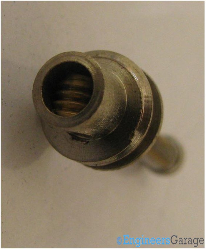
Image of Connector Screw

Fig. 8: Image of Connector Screw

Image of Assembly of Connector Pin and Screw

Fig. 9: Image of Assembly of Connector Pin and Screw

Connecting Screw: The screw is small, its radius approximately [6mm] but it is able to cover the contact pin grove as can be seen in the images above. 

Related Articles Read More >

Insight – How an LED dot matrix display works
Insight – Learn the workings of a capacitive touch sensor
Insight – How Does an Odometer Work
Insight – How Expandable Screw Works

HAVE A QUESTION?

Have a technical question about an article or other engineering questions? Check out our engineering forums EDABoard.com and Electro-Tech-Online.com where you can get those questions asked and answered by your peers!


Featured Tutorials

  • Getting Started with the ESPlorer IDE
  • SENDING TEXT MESSAGE USING ESP8266
  • CONNECTION BETWEEN TWO ESP8266
  • ESP8266 WIFI HOTSPOT
  • HOME AUTOMATION USING ESP8266
  • Open WiFi Scanner using Esp8266

Stay Up To Date

Newsletter Signup

EE Training Center Classrooms

“ee

“ee

“ee

“ee

“ee

Recent Articles

  • How to monitor pH levels in an aquarium using Arduino
  • What are the different types of fingerprint scanners?
  • TV remote hack using Arduino and IR sensor
  • Gesture sensor using Arduino
  • Diodes adds to its family of voltage-level shifters

RSS EDABOARD.com Discussions

  • Self resonant frequency of MLCC capacitor
  • Force sensing resistor (FSR) nonlinearity?
  • Vivado simulation variables
  • Connecting RF Tx/Rx Modules to SMA via PCB and header pin
  • Help to identify circuit took from a mixer

RSS Electro-Tech-Online.com Discussions

  • Help with circuit design
  • How are you managing with the Covid-19 pandemic?
  • Does anyone have a paper tape punch for sale, to suit 1" tape?
  • Would someone be interested in a raspberry pi?
  • Need to add a question to a thread.
Engineers Garage
  • Analog IC TIps
  • Connector Tips
  • DesignFast
  • EDABoard Forums
  • EE World Online
  • Electro-Tech-Online Forums
  • Microcontroller Tips
  • Power Electronic Tips
  • Sensor Tips
  • Test and Measurement Tips
  • 5G Technology World
  • About Us
  • Contact Us
  • Advertise

Copyright © 2021 WTWH Media LLC. All Rights Reserved. The material on this site may not be reproduced, distributed, transmitted, cached or otherwise used, except with the prior written permission of WTWH Media
Privacy Policy | Advertising | About Us

Search Engineers Garage

  • Projects and Tutorials
    • Circuit Design
    • Electronic Projects
      • 8051
      • Arduino
      • ARM
      • AVR
      • PIC
      • Raspberry pi
      • STM32
    • Tutorials
    • Components
  • Articles
    • Tech Articles
    • Insight
    • Invention Stories
    • How to
    • What Is
  • News
    • EE Design News
    • DIY Reviews
    • Guest Post
    • Sponsored Content
  • Forums
    • EDABoard.com
    • Electro-Tech-Online
    • EG Forum Archive
  • Digi-Key Store
    • Cables, Wires
    • Connectors, Interconnect
    • Discrete
    • Electromechanical
    • Embedded Computers
    • Enclosures, Hardware, Office
    • Integrated Circuits (ICs)
    • Isolators
    • LED/Optoelectronics
    • Passive
    • Power, Circuit Protection
    • Programmers
    • RF, Wireless
    • Semiconductors
    • Sensors, Transducers
    • Test Products
    • Tools
  • EE Resources
    • DesignFast
    • LEAP Awards
    • Oscilloscope Product Finder
    • Video
    • White Papers
    • Webinars
  • EE Learning Center
  • Women in Engineering