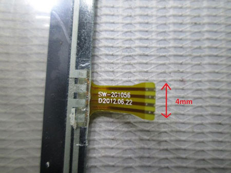
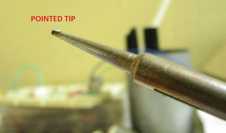
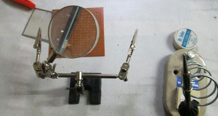
Process
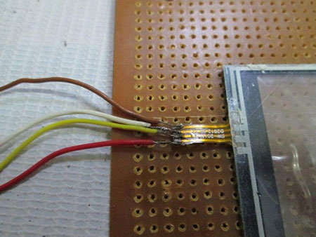
Fig. 4: Image showing connecting wires attached to touch screen

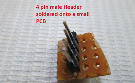
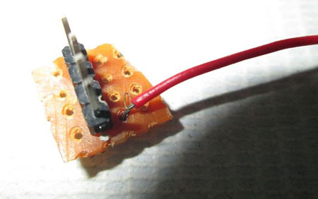

Fig. 8: Image of breakout board
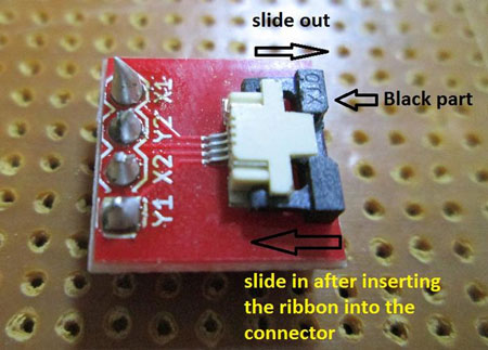
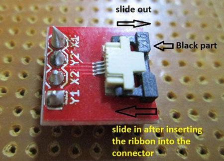
Fig. 9: Typical Image of Breakout Board for 4-wire resistive touch screen

Fig. 10: Image showing cut made of electric tape to cover connections of touch screen

Working

|
ATMega16 Pin
|
Touch Screen Breakout Board Pin
|
Pin Configuration for reading X co-ordinate
|
Pin Configuration for reading Y co-ordinate
|
|
PA1
|
Y1
|
–
|
5V
|
|
PA2
|
X2
|
GND
|
–
|
|
PA3
|
Y2
|
ADC
|
GND
|
|
PA4
|
X1
|
5V
|
ADC
|
Project Source Code
###
/* * touchscrn.c * * Created: 9/14/2013 8:58:01 AM * Author: Ganesh Selvaraj */
#define F_CPU 16000000UL
#define y1 PA1
#define x2 PA2
#define y2 PA3
#define x1 PA4#define USART_BAUDRATE 9600
#define BAUD_PRESCALE (((F_CPU / (USART_BAUDRATE * 16UL))) - 1)
#include <avr/io.h>
#include <util/delay.h>void Init()
{
UCSRB |= (1 << RXEN) | (1 << TXEN); // Enable transmission and reception
UCSRC |= (1 << URSEL) | (1<<USBS) | (1 << UCSZ0) | (1 << UCSZ1);
// Use 8-bit character sizes
UBRRL = BAUD_PRESCALE;
UBRRH = (BAUD_PRESCALE >> 8);
}
unsigned int RdChar()
{
while ((UCSRA & (1 << RXC)) == 0); // wait until data has been received
return(UDR); // return the byte
}void WrChar(unsigned char d)
{
while ((UCSRA & (1 << UDRE)) == 0); // wait till UDR is ready
UDR = d; // send data
}
void WrString(const char *msg)
{
while(*msg!='�')
{
WrChar(*msg);
msg++;
}}
void WrInt(int val,unsigned int field_length)
{
char str[5]={0,0,0,0,0};
int i=4,j=0;
while(val)
{
str[i]=val%10;
val=val/10;
i--;
}
if(field_length==-1)
while(str[j]==0) j++;
else
j=5-field_length;if(val<0) WrChar('-');
for(i=j;i<5;i++)
{
WrChar(48+str[i]);
}
}
void WrCoord(uint16_t x,uint16_t y)
{
WrInt(x,4);
WrChar(',');
WrInt(y,4);
WrChar('r');
WrChar('n');
}void SetADC()
{
ADMUX|=(1<<REFS0);
ADCSRA=(1<<ADEN)|(7<<ADPS0);
}uint16_t ReadADC(uint8_t ch)
{
//Select ADC Channel ch must be 0-7
ch=ch&0b00000111;
ADMUX&=0b11100000;
ADMUX|=ch;
//Start Single conversion
ADCSRA|=(1<<ADSC);//Wait for conversion to complete
while(!(ADCSRA & (1<<ADIF)));//Clear ADIF by writing one to it
ADCSRA|=(1<<ADIF);return(ADC);
}
void Waiting(int j) // simple delay function
{
uint8_t i;
for(i=0;i<j;i++)
_delay_ms(200);
}int main(void)
{
uint16_t x,y;
Init();SetADC();
while(1)
{DDRA=((1<<x1)|(1<<x2));
PORTA=((0<<x2)|(1<<x1));
_delay_ms(10);
x=ReadADC(3);
DDRA=((1<<y1)|(1<<y2));
PORTA=((1<<y1)|(0<<y2));
_delay_ms(10);
y=ReadADC(4);
WrCoord(x,y);
Waiting(1);
}
}###
Circuit Diagrams
Filed Under: Electronic Projects


Questions related to this article?
👉Ask and discuss on EDAboard.com and Electro-Tech-Online.com forums.
Tell Us What You Think!!
You must be logged in to post a comment.