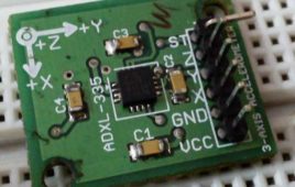
This project makes use of three out of the eight ADCs present in AtMega16 IC to display the corresponding digital data of X, Y and Z outputs of an accelerometer on 16X2 LCD.It’s very easy to deal with such kind of modules as they just need the VCC and GND supply to get started, rest it is its job to provide us the analog data.These modules work on simple concept like that of force acting on an object at inclined plane. It deals with the Mg(sin ?) and Mg(cos ?) part of the force and calculate the angle ? for further calculations. Now it also notices the change in force from which acceleration will be calculated.
Fastest Finger First Circuit using ATMega16
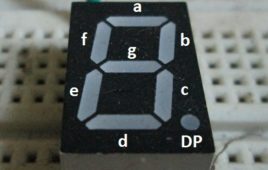
Fastest Finger first circuit is basically used in quiz type games where the reaction speed of a participant is significant. The circuit enables us to identify who responded first to the question by triggering a visual and audio indication. The circuit uses a buzzer to produce the audio signal and a seven segment display for visual indication. The display shows the corresponding team number which pressed the buzzer first. The brain of this circuit is an ATMega16 microcontroller which can run at a maximum speed of 16MHz and so there will be no question of clash between any two contestants until and unless their reaction time was same in order of microseconds which is impossible. Continue reading to find out what the circuit components are and how it is assembled as well as put to work.
Sleeping Security – Smart Keypad Lock using AtMega16
This project is just a smart version of any keypad lock. What’s smart about it is that it can detect whether it is needed by the user or not and accordingly switches itself to take a sleep. Making a microcontroller to sleep reduces power consumption as well as increases its usage span.Many of you must be wondering that would it be secure enough to make a lock go to sleep, isn’t it. Don’t worry, when a microcontroller goes off to sleep it puts a hold on what it was doing before sleeping. In my project I have made it to sleep only when the user has finished entering the password stuff and microcontroller has done its entire job.
GSM Based AC Appliance Control
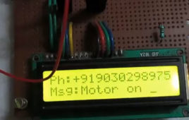
This project would show you how to control an AC appliance remotely from anywhere using your mobile phone. This kind of project is useful in various applications. Say for example a farmer can switch ON or OFF the motor pump present near his field remotely. In this way he need not travel all the way to the field to control it, especially at night times.
GSM Based Intruder Alerting System
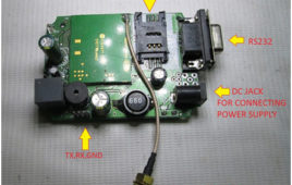
Did you know that most of the thefts at home happen when it is empty? But not everyone is rich enough to hire a security for their house and at the same time they themselves cannot be at home 24 by7. Now what if there is a system which alerts you about an intruder through a text message?The following tutorial teaches how to make you own intruder alerting system
4 Wire Touch Screen Based Digital Magic Slate
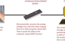
Ever played with magic slates in your childhood? Well this project will show you how to make a digital magic slate using a PC, a touch screen and few other components. Basically the project converts the analog voltage coming from the resistive touch screen into a two co-ordinate integer value and sends it to the PC through the microcontroller. The processing code takes these co-ordinates as inputs and draws a white dot for each co-ordinate, on the output screen.So when you write continuously on the touch screen, the dots would be plotted close enough to make it look like a line or curve. The circuit is based around a Atmega 16 micro controller, Serial to USB converter or (Serial to RS-232 + RS-232 to USB converter) along with a personal computer or a laptop.
Speed and Direction Control of DC Motor using AVR Microcontroller – (Part 20/46)
we can count number of such applications where there is a need to change direction and/or speed of DC motor. The direction of DC motor can be controlled by just reversing the polarity of given supply. And for varying speed, there are various ways to vary speed of DC motor but the best amongst them is PWM – pulse width modulation technique. In this technique we shall vary the width of applied pulse that will vary average voltage applied to motor and its speed will change.
Speed and Direction Control of Stepper Motor using AVR Microcontroller- (Part 25/46)
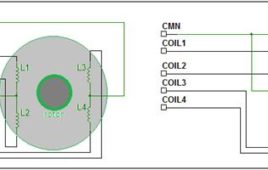
Stepper motor can be termed as digital motor because it operates on pulses. Unlike AC or DC motor that rotates continuously, stepper motor rotates in steps. It rotates in number of steps as per applied number of pulses. The common terminal is connected to –Ve (Gnd) terminal.So as we apply this four steps sequence continuously, the motor will rotate clockwise or anticlockwise. Now to change the speed of motor we have to change pulse repetition frequency (PRF) that is the frequency of applied pulses. If PRF is increased the pulse duration decreases and speed increases and vice versa. So this project demonstrates how to vary the speed and change the direction of given stepper motor using AVR microcontroller ATmega32
Controlling RGB LED colour using Atmega16- (Part 19/46)
This tutorial will give you a brief introduction to the concept of colors and how different colors can be produced using RGB LED. The color would be controlled using an ATMega16 microcontroller.RGB LEDs are basically the combination of the 3 LEDs (Red, Green and Blue) fused into a single package. It consists of four pins totally out of which three of them for the three different colors. The 4th pin is common for all three colors and it’s either Cathode or Anode.
Latitude & Longitude Display System Using GPS & AVR Microcontroller- (Part 44/46)
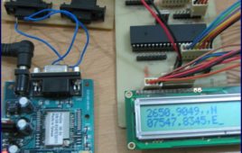
This project is a reference to budding engineers or a helping hand to those who willing to work and interface a GPS Receiver with microcontroller and making their own channel to communicate with satellite, seeking for some useful information from satellite to make a effective and efficient system. Before we check all the details of this project, here is the final implemented circuit diagram of longitude and latitude display system using GPS and AVR microcontroller.
embRACE: The Embedded Race
embRACE, a game developed on the embedded platform, entirely coded in assembly language. The game has been programmed on an ATMega16 micro-controller, interfaced with a 16×2 LCD display module.The LCD display uses custom LCD characters to display various characters in the game whose generation timing in the game is totally randomized by the code. In the design and code phase it has particularly been taken care of that the overall game is interesting and substantially user-interactive.
DIY: Retro Style Analog Volt Meter using Servo Motor
Digital equipments have rapidly replaced Analog equipments in the long run. Well that is because the former has lot of advantages over the latter. But do you miss those retro style analog measuring instruments? Those pointy indicators and graduated scales? Well I do and so have decided to build one with the “modern” parts. This article will show you how to make a Retro Style D.C. Voltmeter which can measure in range of 0-30V.
Interfacing 4-wire Resistive Touchscreen with ATMega16 Microcontroller- (Part 46/46)
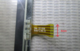
In this tutorial we’ll learn how to interface a 4-wire Resistive touch screen with ATmega16 microcontroller. Touch screens are two dimensional input devices. Nowadays most of the electronic gadgets use them. Laptops, smart phones, tablets and even some home appliances like washing machines & microwave ovens also use a touch screen nowadays. Touch screens are preferred over keypads because they need very little or no pressure to operate whereas the Keypads/ buttons need a minimum pressure to operate and our hands start aching after some time of continuous usage.One more great advantage in using a touch screens is that it enables us to make more room for the screen itself instead of wasting the space on the permanent keypad. That’s the reason for our smart phone’s screens to become big enough to browse web pages also and still fit in our pockets.
Interfacing Serial Bluetooth Modem with Computer using ATmega16- (Part 41/46)
This project would give you a general idea about how to setup and interface any Bluetooth modem with your computer. There are many types of Bluetooth modems available in market, which vary in quality, cost, range, etc. Some of the well known Serial Bluetooth modems are AUBTM, BLUESMIRF, RN-41, HC-05 and HC-04.I would be using the last one i.e. the cheap Chinese Bluetooth module. It has limited functions and it can only work in slave mode. (Remember: Two slave modules cannot directly communicate to each other so be careful when you buy them.) The top range modules have a facility to work in both MASTER and SLAVE modes. It is Class 3 module so it range is very low. (Class 2 has a range of 10 meters and Class 1 has a range of 100 meters.)
AVR ATmega16/32 Fuse Bits
Summary Updating with the era of technology, the new microcontrollers are coming with lots of inbuilt peripherals and features. These inbuilt peripherals and features not only reduce the cost of additional circuits to be used with the controller but also provide an ease to interface additional devices (such as Modems etc) directly with the microcontroller. The…
How to interface GPS with AVR microcontroller (ATmega16)- (Part 43/46)
GPS modem is a device which receives signals from satellite and provides information about latitude, longitude, altitude, time etc. The GPS navigator ismore famous in mobiles to track the road maps. The GPS modem has an antenna which receives the satellite signals and transfers them to the modem. The modem in turn converts the data into useful information and sends the output in serial RS232 logic level format. The information about latitude, longitude etc is sent continuously and accompanied by an identifier string.This article shows how to interface the GPS modem with ATmega16 and extract the location (latitude and longitude) from the GPGGA string and display it on LCD. The connection of GPS modem with AVR microcontroller (ATmega 16) is shown in the circuit diagram. The ground pin of max 232 and serial o/p of GPS modem is made common. Pin2 of MAX232 is connected to pin 3 of GPS modem and pin 3 of max 232 is connected to pin 2 of modem. This type of connection is called a serial cross cable.
How to configure Watchdog Timers of AVR Microcontroller (ATmega16)- (Part 15/46)
Some high end applications require multiple or critical calculations to be done by the microcontroller. This may lead to cases when the controller enters intowrong or infinite loops. As a result of this, the system either hangs up or gets crashed. The solution to overcome these situations is to automatically reset the system whenever such a situation arises.The Watchdog Timer is a hardware or software generated timer interrupt which reboots/resets the system in the situations mentioned above. The watchdog timers are also used in cases when you intentionally require resetting the system without any physical interference.The AVR microcontroller has an in-built watchdog timer. This article explains the working of watchdog timer in ATmega16. The Watchdog Timer is a special timer which can be enabled in any section of the code and when enabled it ensures that a certain number of instructions execute within a pre-defined time frame. This time frame or the time delay can be configured/set using the registers of the watchdog timer.
How to interface serial ADC0831 with AVR microcontroller (ATmega16)- (Part 27/46)
ADC is an electronics device that converts the analog signals to digital number proportional to the magnitude of voltage. The ADClike ADC0804, ADC0809 etc., give 8-bit digital output. The controller device needs eight pins to receive the 8-bit data (For more details about ADC refer to Using Inbuilt ADC of AVR). Some applications need higher resolution ADCs, (10 or higher bits digital data output) for data accuracy. Using parallel ADCs is one option for such applications. However using parallel ADC will increase the size of the hardware as a 10-bit parallel ADC will have 10 output lines. Also you might have to use controller with higher number of pins. The other option is to use serial ADC, which needs smaller number of pins. Since the data is transmitted serially, the data transfer rate of the serial ADC is low as compared to parallel ADC. They can serve as a very good alternative in applications where speed of data transfer in not a critical point. This article explores interfacing of serial ADC0831 with ATmega16.
How to take input from a particular pin of ATmega16- (Part 5/46)
For understanding the human needs a system must be able to take input from user. The devices which can be used to take input for a system are keypad, touch [[wysiwyg_imageupload::]]screen, etc. In the article LED blinking, the microcontroller drives the LED or in embedded language the microcontroller was set to give o/p, this article gives brief information of getting an input from user at a particular pin of microcontroller. In order to take input from an external source on any of the pins of the AVR microcontroller, the pins need to be configured as input pin. This configuration informs the controller that the corresponding pins are used to take input. Read more to find out how the circuit is constructed and how the IC can be programmed to work in the desired manner.
How to interface Servo Motor with AVR Microcontroller (ATmega16)- (Part 21/46)
Servo motors find huge applications in industries in the field of automation, control & robotics. The servo motors are well known for their precise control and work [[wysiwyg_imageupload::]]on the principle of servo mechanism. The servo motors can be made to run at precise angle using PWM. The PWM (pulse width modulation) is the basic working principle behind a servo motor (For more details about PWM refer Phase correct PWM mode). This article explores the interfacing of servo motor with ATmega16. Also to know more about servo mechanism see Interfacing Servo Motor with 8051. There are different types of servos available in the market. This article bounds its scope to interfacing a commonly available servo, widely used by hobbyist with ATmega16. Such a servo consists of three wires positive supply, ground and a control signal. Unlike other motors, Servo motors don’t require any driver. When a PWM signal is applied to its control pin the, the shaft rotates to a specific angle depending on the duty cycle of the pulse.

