This project is a reference to budding engineers or a helping hand to those who willing to work and interface a GPS Receiver with microcontroller and making their own channel to communicate with satellite, seeking for some useful information from satellite to make a effective and efficient system.
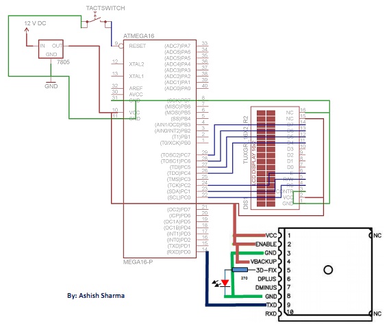
Before we check all the details of this project, here is the final implemented circuit diagram of longitude and latitude display system using GPS and AVR microcontroller.
Fig. 1: Prototype of AVR ATMega16 based GPS Receiver
GPS
In a simplest way ‘The Global Positioning System (GPS)’ is a satellite-based navigation system that consists of 24 orbiting satellites. This satellite transmits an amount of information in string format (e.g.: latitude, longitude, altitude, time etc.) which we are going to cover further.
GPS Receiver
GPS Receiver received the information in string format, transmitted by Satellites, which uses this information to calculate different parameters between it and satellites. With information from satellites, a GPS receiver can fix its location on the ground from the known position of the satellites.
Now I want to drag your attention on the purpose of this project. In this project, we are going to display ‘Latitude & Longitude’ used for positioning of an object on the earth. So let’s talk about how a GPS receiver fixes its location on the ground, as i above said and the find the location of an object on the earth.
Position Locator
Let me tell you, if we want an object location on the earth, GPS receiver have to connect with minimum 3 Satellite at the point of time. Now i explain this in a simple way by the help of fig 1.1:
Fig. 2: Diagram showing Position Location by two Satellites
In Fig 1.1, I am trying to symbolize ‘Earth with a Sky Blue Circle’, ‘Satellites with Dark Blue’, ‘Satellites radius with Black outline circle’ and the ‘position with small Red circle’.
So let us assume we are standing on the earth with GPS Receiver and receiver is connected with two satellites- Satellite 1 and Satellite 2 at the time of instant. Both satellites have its own radius and after connecting with GPS Receiver, both radius will intersect with two points. This means we got two positions of us with respect to satellite at the same point of time which is practically not possible. So we will not able to fix our fix position in this case.
Fig. 3: Diagram showing Position Location by three Satellites
Problem solved. If our GPS receiver is connect with minimum 3 satellite at point of time, we got three radius by Satellite 1, Satellite 2 and Satellite 3, and all three radius will intersect in a common point and that common intersect point is our fix location on the earth with respect to satellites, that I meant in the starting of this section. I hope now you will be able to understand the concept.
INFORMATION TRANSMITTED BY SATELLITES
A list of information as string format given by Satellites as shown below in Table-1:
Fig. 4: Table listing NMEA Output Sentence
Along with this information, we need to find position which the ultimate purpose of our project, so we are going use only ‘GGA’ string. All string starts with ‘$GP’ which is a “talker ID” a two-character prefix that identifies the type of the transmitting unit. By far the most common talker ID is “GP”, identifying a generic GPS. The detailed description of ‘$GPGGA’ string is given below in Table-2 and Table-3:
Fig. 5: Table listing GGA Data Format
GPS Receiver
BLOCK DIAGRAM
Fig. 6: Block Diagram of AVR ATMega16 based GPS Receiver
GPS RECEIVER
For this project, i am using GPS Receiver named “GTPA010 GPS Receiver with Embedded Antenna (FGPMMOPA6E)”. This is a Micro GPS Module has the following features.
*Note that it has an onboard antenna – no need to connect a separate antenna.
Fig. 7: Typical Image of GTPA010 GPS Receiver
FEATURES
|
CPU |
|
|---|---|
|
Processor |
ARM7EJ-S |
|
Technical |
|
|
Digital I/O Type |
3.3V TTL |
|
IC used |
MTK MT3329 |
|
Relative Humidity |
5% to 95% (no condensing) |
|
Sensitivity |
Acquisition?-148dBm (Cold Start), Reacquisition?-160dBm 1, Tracking?-165dBm |
|
Frequency |
L1, 1575.42MHz, C/A Code – 1.023 MHz |
|
Features |
|
|
Other |
WAAS, EGNOS,MSAS ,GAGAN supported, Position Accuracy – 3m, Hot start: 1.0s, Warm start: 34s, Cold start: 35s, Protocols: NMEA 0183 v3.01 (Default?GGA,GSA,GSV,RMC,VTG), MTK NMEA Command |
|
Wireless |
|
|
Channels |
66 Channels |
|
Communications |
|
|
Communication Interface |
UART Interface – TTL level serial port |
|
Data Transfer Rate |
Default?9600bps, (4800/9600/38400/57600/115200 bps by customization) |
|
Power Supply |
|
|
Operating Voltage |
3.2V to 5.0V (Typical?3.3V) |
|
Operating Current |
<30mA at 3.0V |
|
Power |
100mW |
|
Physical |
|
|
Connectors |
1 x 10pins Header |
|
Package Contains |
1 x 433MHz SI4432 Wireless Transceiver Module |
|
Range |
3m Position Accuracy |
|
Operating Temperature |
-40°C to +85°C |
PINOUT
Out of these 10 pins, i use 7 pins for this project. Pins names are:
1) VCC 2) ENABLE 3) GND 4) VBACKUP 5) 3D-FIX 6) GND 7) TXD
1) VCC: The main DC power supply for the module. The voltage should be kept between from 3.6V to 5V. The ripple must be controlled under 50mVpp. Connect it to microcontroller VCC Pin.
2) ENABLE: With a low level, it causes the module to reset. Connect it to VCC Pin.
3) GND: Ground. Connect it to microcontroller ground pin.
4) VBACKUP: This is the power for GPS chipset to keep RTC running when main power is removed. The voltage should be kept between 2.0V~4.3V, Typical 3.0V. If Vbackup is no supplied with power, GPS module will revert back to default setting and perform cold start when re-started. Connect it to VCC Pin.
5) 3D-FIX: The 3D-FIX was assigned as fix flag output, if not used, keep floating.
Before 2D Fix :
Fig. 9: Diagram of signal before 2D or 3D Fix
The pin should continuously output one-second high-level with one-second low-level signal.
After 2D or 3D Fix
Fig. 10: Diagram of signal after 2D or 3D Fix
The pin should continuously output low-level signal.
So i connect a LED with this pin, as shown in schematic diagram below, to check the whether GPS data is fix or not.
6) GND: Ground. Connect it to microcontroller ground pin.
7) TXD: This is the UART transmitter of the module. It outputs the GPS information for application.
Power Supply
POWER SUPPLY
Power supply for the complete unit can be derived from the mains using a step-down transformer of 230V AC primary to 0-12V, 500mA secondary. A full- wave rectifier followed by a capacitor filter is the output voltage and feeds it to the 5-volt regulator (LM7805) whose output is used to the power supply requirements of microcontroller circuit, other IC’s.
Fig. 11: Circuit Diagram of Power Supply for GPS Receiver
Fig. 12: Prototype of Power Supply for GPS Receiver
Working Principle
As shown in schematic, I have connected GPS VCC, ENABLE, VBACKUP pins to Microcontroller’s VCC, GPS GND pins to Microcontroller’s GND pin and GPS TXD pin to Microcontroller’s RXD pin (e.g. PD0 pin) because whenever GPS transmits data, Microcontroller received that data.
This type of communication is called ‘USART Communication’ based on ‘RS-232 Protocol’ which is simplest way to communicate with such type of devices for a beginner which provides USART output or input.
(*NOTE: If you are not aware of USART Communication, please go through its tutorials which are easily available on web or ‘Engineers Garage’ official website.)
When you power up, the red LED connected with GPS Receiver is start blinking because GPS Receiver position is not fix at this time. So wait for LED blinking to be stop. When LED Blinking is stop, means GPS Receiver now fixed its position and the information provided by it is a valid information at this time.
The following algorithm is used to extract the latitude and longitude information from the GPS module using $GPGGA string and display it on a LCD:
1. Receive data from GPS and check weather that data is equal to $. If the data matches go to next step else wait for $.
2. Check data continuously and check if the received byte is equal to GPGGA
3. If the step (2) matches completely then go to step (4) else go back to step (1)
4. Leave first comma and wait till second comma (since we not looking for time).
5. Start taking data in an array lati_value[ ] till the next comma.
6. Get latitude direction in lati_dir
7. Do the same for longitude
8. Display the values on LCD and go back to step (1).
You will get following result on LCD:
Fig. 13: Image of LCD Module displaying Lattitude and Longitude received from AVR ATMega16 based GPS Receiver
Congratulation!!!! We have successfully done this project.
CONCLUSION
A position locator can be easily implemented with the grouping of simple controls and basic knowledge of interfacing devices and USART communication or it can be more compelled if we are going to use some other parameters with the same time.
Well more knowledge is gained and more experiences are faced. Lot of information’s are collected ultimately, I have concluded with a great pleasure for achieving my aim.
Project Source Code
###
#define F_CPU 4000000UL #include<avr/io.h> #include<util/delay.h> #include<lcd_lib.h> #define USART_BAUDRATE 9600 #define BAUD_PRESCALE (((F_CPU / (USART_BAUDRATE * 16UL))) - 1) void usart_init(); unsigned int usart_getch(); unsigned char value,lati_value[15],longi_value[15],lati_dir,longi_dir; int i,j; int main(void) { int rem=0; LCDinit(); LCDclr(); LCDGotoXY(0,0); LCDstring("Cordi :",7); usart_init(); while(1) { value=usart_getch(); if(value=='$') { value=usart_getch(); if(value=='G') { value=usart_getch(); if(value=='P') { value=usart_getch(); if(value=='G') { value=usart_getch(); if(value=='G') { value=usart_getch(); if(value=='A') { value=usart_getch(); if(value==',') { value=usart_getch(); while(value!=',') { value=usart_getch(); } lati_value[0]=usart_getch(); value=lati_value[0]; for(i=1;value!=',';i++) { lati_value[i]=usart_getch(); value=lati_value[i]; } lati_dir=usart_getch(); value=usart_getch(); while(value!=',') { value=usart_getch(); } longi_value[0]=usart_getch(); value=longi_value[0]; for(i=1;value!=',';i++) { longi_value[i]=usart_getch(); value=longi_value[i]; } longi_dir=usart_getch(); LCDGotoXY(0,0); j=0; while(lati_value[j]!='�') { LCDsendChar(lati_value[j]); j++; } LCDsendChar(lati_dir); LCDGotoXY(0,1); _delay_ms(1000); i=0; while(longi_value[i]!='�') { LCDsendChar(longi_value[i]); i++; } LCDsendChar(longi_dir); _delay_ms(1000); } } } } } } } } } void usart_init() { UCSRB |= (1<<RXCIE) | (1 << RXEN) | (1 << TXEN); UCSRC |= (1 << URSEL) | (1 << UCSZ0) | (1 << UCSZ1); UBRRL = BAUD_PRESCALE; UBRRH = (BAUD_PRESCALE >> 8); } unsigned int usart_getch() { while ((UCSRA & (1 << RXC)) == 0); return(UDR); }###
Circuit Diagrams
Filed Under: Electronic Projects

Questions related to this article?
👉Ask and discuss on EDAboard.com and Electro-Tech-Online.com forums.
Tell Us What You Think!!
You must be logged in to post a comment.