What is the Hall Effect Sensor/Device
A device which converts magnetic or magnetically encoded information into electrical signals is called HALL EFECT SENSOR. A Hall Effect device/sensor is a solid state device that is becoming more and more popular because of its many uses in different types of applications. Hall Effect devices are immune to vibration, dust and water.

Brief History

It was Prof. Edwin Hall an American physicist while experimenting in his Lab; Hall used a thin Gold foil and in 1879 discovered for the first time that an electric potential acting perpendicularly to both the current and the magnetic field. The effect has since been known as the Hall Effect. Hall discovered that charge carriers moving along the conductor experience a transverse force and tend to drift to one side and this movement of charge carriers induces a voltage on the conductor known as Hall voltage. VH

How Hall Effect Sensor works
The Basic Principle of Hall Effect is the activation by an external magnetic field. As we are familiar that there are two important characteristics of a magnetic field.
Viz. Flux density, (B) and polarity (North & South Poles).
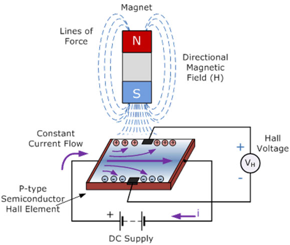
When the magnetic flux density around the sensor exceeds a certain preset threshold, the sensor detects it and generates an output voltage called the Hall Voltage, VH. The following diagram shows a basic function of a Hall Effect Sensor.
Inside a Hall Effect Sensor
Inside a Hall Effect Sensor
A Hall Effect Sensor consists of a thin piece of rectangular p-type semiconductor material. There are four following semiconductors used in Hall Effect devices
1: Gallium arsenide (GaAs),
2: indium antimonide (InSb)
3: indium arsenide (InAs)
4: Silicon si
Indium antimonide (InSb) & indium arsenide (InAs) are most commonly used because of its high electron mobility.

So passing a continuous current through these semiconductors. When the device is placed within a magnetic field, the magnetic flux lines exert a force on the semiconductor material which deflects the charge carriers, electrons and holes, to either side of the semiconductor slab. This movement of charge carriers is a result of the magnetic force they experience passing through the semiconductor material. As these electrons and holes move side wards a potential difference is produced between the two sides of the semiconductor material by the build-up of these charge carriers. Then the movement of electrons through the semiconductor material is affected by the presence of an external magnetic field.
Since the Hall element reacts to the magnetic flux perpendicular to its surface, therefore, the position and placement of the Hall element in the IC in relationship to the magnet field of the magnet (the placement of the magnet and its magnetic strength) is important for the correct operation of the IC. The following diagram shows the operation of Hall Effect device.
To generate a potential difference across the device the magnetic flux lines must be perpendicular, (90o) to the flow of current and be of the correct polarity, generally a south pole. The Hall Effect provides information regarding the type of magnetic pole and magnitude of the magnetic field. For example, a south pole would cause the device to produce a voltage output while a north pole would have no effect. Generally, Hall Effect sensors and switches are designed to be in the “OFF”, (open circuit condition) when there is no magnetic field present. They only turn “ON”, (closed circuit condition) when subjected to a magnetic field of sufficient strength and polarity.
Block Diagram & Circuit of Hall Effect Sensor
Block diagram of Hall Effect sensor
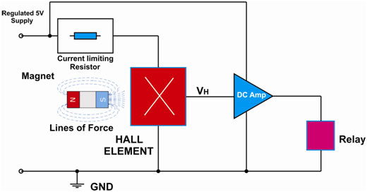
The above diagram shows that the output voltage, called the Hall voltage, (VH) of the basic Hall Element is directly proportional to the strength of the magnetic field passing through the semiconductor material. This output voltage is very small in our project, about 50 to 80mv even when subjected to strong magnetic fields. Therefore a DC Amp is used to improve the sensor’s sensitivity, hysteresis and output voltage. This also allows the Hall Effect sensor to operate over a wider range of power supplies and magnetic field conditions.
Commonly Hall Effect devices cannot be designed to directly switch large loads as their output current drive capabilities are limited between10 to 50mA, depends upon the collector current of transistor. Therefore to drive large currents it is recommended to use a relay as is the case in this project.
Electrical circuit diagram of Hall Effect sensor
Circuit Description
The circuit shown in the circuit diagram tab is a complete hall sensor switch. The regulated DC supply voltage is directly applied to the hall element through R1 current limiting resistor. Capacitor C1 is used to attenuate the random noise of electrons which may affect the output hall voltage at pin No 3.
Pin No 3 is the Hall output voltage. T1 is an NPN transistor which is used to saturate in presence of external magnetic field. R2 provides bias to the collector of T1. Transistor T2 drives the relay. D1 is a protection diode used to protect against the counter EMF generated by the relay coil. RL is a relay which drives the output load.
Working & Applications
WORKING
When a magnet is put over the Hall sensor. The sensor detects the external magnetic field which causes the voltage to appear at pin No 3 of Hall element. This voltage is very small to drive the load, therefore transistor T1 is used as a DC amplifier which drives the base of transistor T2. When the base of transistor T2 becomes more negative it causes the transistor to saturate and drives the relay. Finally the load either AC or DC can be directly connected to the relay.
Features
1. Low cost. Less than INR 40.00
2. Simple circuit. No operational amplifier is used.
3. Low voltage operation.
Parts List
1. R1= 1K
2. R2= 1.5K
3. C1= 0.1uF
4. T1= NPN general purpose Transistor BC547
5. T2= PNP general purpose Transistor BC557
6. D1= 1N4007
7. RL= Relay. Coil Resistance=500 Ohms, Voltage=6V O/P Load Current rating= 5 to10Amps.
8. H1 is a Hall sensor.
Note: Any Hall sensor can be used. It is a good Idea to extract Hall sensor from an old junk of CD ROM/ Floppy drive, VCR capacitan motor or any other stepper motors. For more details please consult the data sheet of the particular part.
Applications
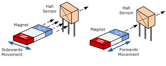
Hall Effect sensors are widely used in many applications. Such as door switches in refrigerators, sliding switch in cell phones, velocity or directional movement for sensing of position in automotive systems, Distance and speed, etc.
The device can be operated by a single permanent magnet attached to a sliding door, moving shaft or any other device. There are many different types of magnet movements, such as “Head-on”, “Sideways”, “Push-pull” or “Push-push” etc. Following diagram shows Head-on Detection & Sideways Detection.
Project Source Code
Circuit Diagrams
Filed Under: Electronic Projects

Questions related to this article?
👉Ask and discuss on Electro-Tech-Online.com and EDAboard.com forums.
Tell Us What You Think!!
You must be logged in to post a comment.