Engineers Garage

  • Electronics Projects and Tutorials
    • Electronic Projects
      • Arduino Projects
      • AVR
      • Raspberry pi
      • ESP8266
      • BeagleBone
      • 8051 Microcontroller
      • ARM
      • PIC Microcontroller
      • STM32
    • Tutorials
      • Audio Electronics
      • Battery Management
      • Brainwave
      • Electric Vehicles
      • EMI/EMC/RFI
      • Hardware Filters
      • IoT tutorials
      • Power Tutorials
      • Python
      • Sensors
      • USB
      • VHDL
    • Circuit Design
    • Project Videos
    • Components
  • Articles
    • Tech Articles
    • Insight
    • Invention Stories
    • How to
    • What Is
  • News
    • Electronic Product News
    • Business News
    • Company/Start-up News
    • DIY Reviews
    • Guest Post
  • Forums
    • EDABoard.com
    • Electro-Tech-Online
    • EG Forum Archive
  • DigiKey Store
    • Cables, Wires
    • Connectors, Interconnect
    • Discrete
    • Electromechanical
    • Embedded Computers
    • Enclosures, Hardware, Office
    • Integrated Circuits (ICs)
    • Isolators
    • LED/Optoelectronics
    • Passive
    • Power, Circuit Protection
    • Programmers
    • RF, Wireless
    • Semiconductors
    • Sensors, Transducers
    • Test Products
    • Tools
  • Learn
    • eBooks/Tech Tips
    • Design Guides
    • Learning Center
    • Tech Toolboxes
    • Webinars & Digital Events
  • Resources
    • Digital Issues
    • EE Training Days
    • LEAP Awards
    • Podcasts
    • Webinars / Digital Events
    • White Papers
    • Engineering Diversity & Inclusion
    • DesignFast
  • Guest Post Guidelines
  • Advertise
  • Subscribe

Digital Multimeter DIY project using microcontroller

By EG Projects May 30, 2019

This project by a student of university of liverpool is about building a digital multimeter using mbed microcontroller. Multimeter can measure three parameters voltage, resistance and capacitance. Measured voltage, capacitance and resistance is  displayed on a 16×2 lcd display. Its a small and cool diy electronics embedded system project.

How multimeter is made? Mbed microcontroller

Mbed microcontrollers are low powered and high performance modules. They posses low latency and high through put. For this particular project their ARM Mbed NXP LPC1768 cortex-m3 variant is utilized. Clock frequency of this particular microcontroller/processor is 96MHz. High clock frequency and through put is what made this microcontroller perfect for digital multimeter application. The mbed microcontroller kit is operating on 3.3 volts.  

How multimeter is measuring resistance, capacitance and voltage?

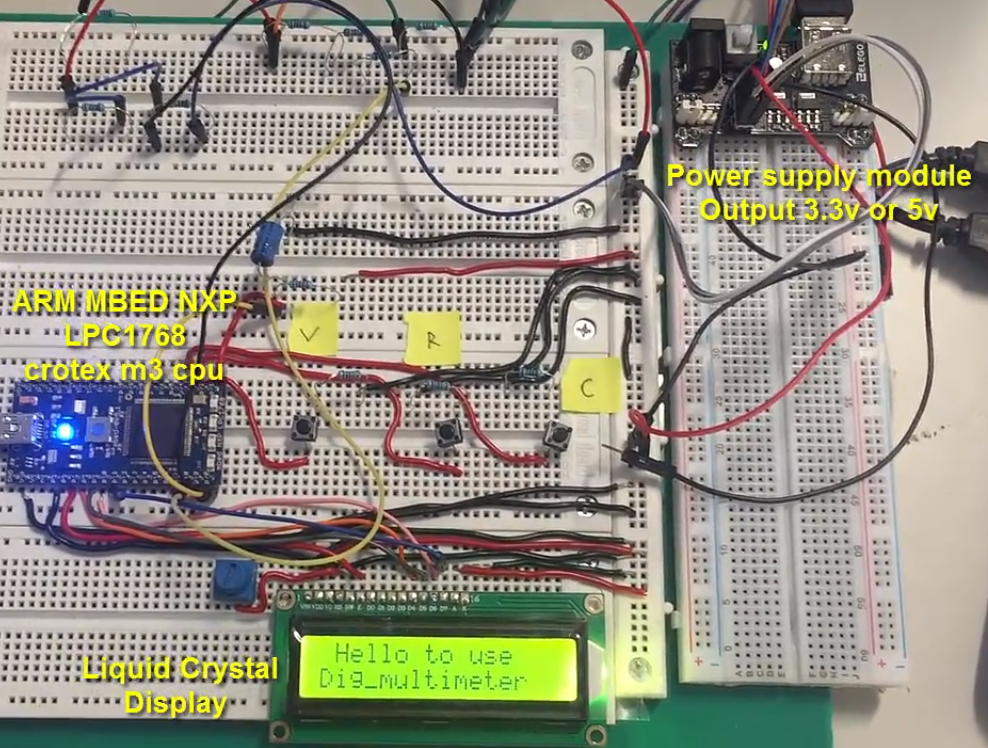
Circuit diagram of the project is given below. A snap shot of the end hardware design is shown in the picture below. A small power supply is mounted on a board and power is taken to other rails using jumper/connecting wires. Mbed microcontroller is housed on an another board along with 16×2 lcd display. To fade or control the brightness of lcd display a variable resistor is installed near the lcd display.

Three push buttons labeled V, R and C sticked with the board represents voltage, resistance and capacitance. Each push button calculates the parameter which is labeled on it.   

Digital multimeter with Mbed microcontroller circuit diagram

Digital multimeter with Mbed microcontroller circuit diagram

Digital multimeter measuring voltage

To measure voltage across a point voltage divider circuit is utilized. For example we want to measure a voltage across point and the max voltage which can arrive at that particular point is 12 volts.
Voltage divider to fix voltage

Voltage divider to fix voltage

Mbed microcontroller is operating on 3.3 volts. Its digital as well as analog pins can sink 3.3 volts. Any voltage greater than 3.3 can severely damage the micrococntroller pins. In this case we use a voltage divider circuit. Voltage is divided across two resistances. The voltage divider circuit is designed in such a way that the voltage across one of the resister never increases the 3.3 voltage range. One must pick the resistance according to it. Voltage divider circuit is given on the left hand side. If we take the picture under consideration according to the above scenario. Then at Vin we have 12 volts. At Vr1 8.7 volts must drop and Vr2 must not increase 3.3 volts in any case.
We want to measure voltage at point Vin. But since the voltage is higher at this point so in order to lower it we divided the voltage. Now how to accurately predict the voltage? A ratio must be calculated between the two resistances R1 and R2. This ratio multiplied with the calculate voltage across R2 or Vr2 yields the final voltage across Vin.  

I made really a nice tutorial on it using arduino i suggest you to go with it for better understanding the method Arduino battery voltage monitor. The result of the voltage measuring is displayed on the 16×2 lcd shown in below picture.

Digital multimeter with microcontroller - Voltage measurement result

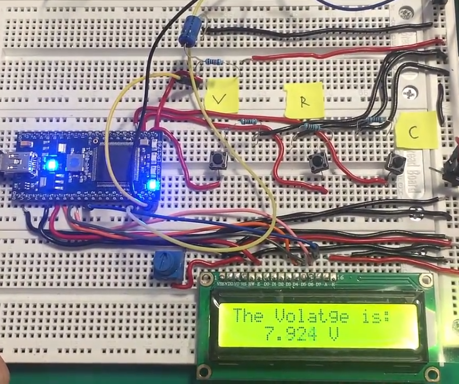
Digital multimeter with microcontroller – Voltage measurement result

Multimeter measuring resistance like OHM meter

Measuring resistance is same like voltage measurement but this time instead of voltage we calculate the resistance after measuring the voltage drop across R2.  
In this case Vin is fixed suppose 12 volts. We also know the R1 resistance. We measure the voltage across R2. Now we three parameters Vin, Vout and R1. Substituting these parameters in the formula given on the right hand yields the resistance of R2.

Note: Care must be taken in measuring the resistance. Vr2 must not increase the 3.3 volts limit. I would suggest you to calculate a range of resistance manually which can be measured relative to the R1. Resistance calculation and result is displayed on 16×2 lcd display. Result can be seen in the picture below.   

Resistance measurement using resistor divider circuit technique

Resistance measurement using resistor divider circuit technique

Digital multimeter with microcontroller - Resistance measurement result

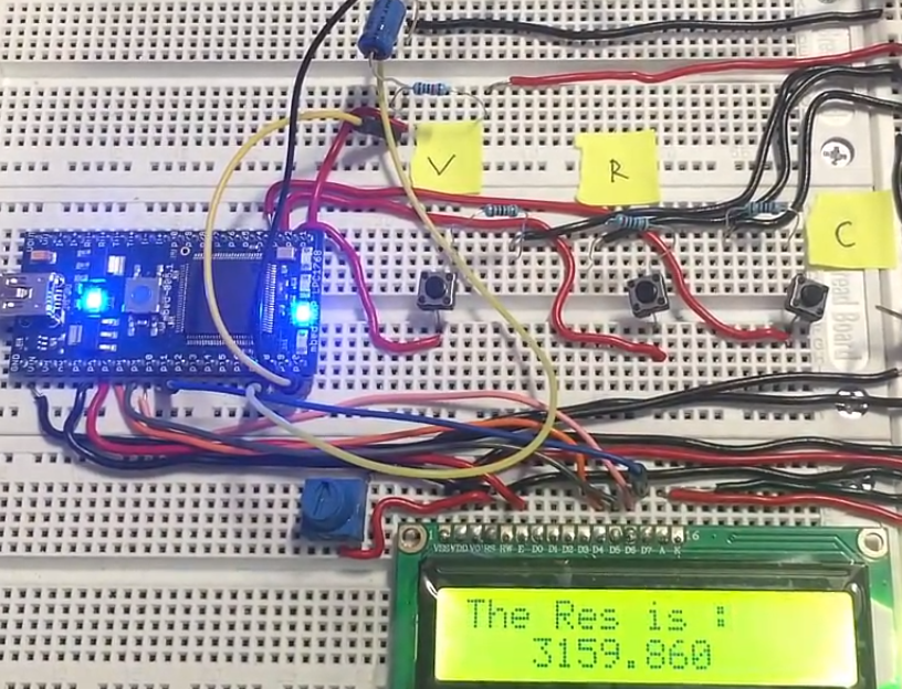
Digital multimeter with microcontroller – Resistance measurement result

Multimeter capacitance measurement

Capacitance is the ability of a discrete electronic component to store charge in it and release when instructed. Capacitors are widely used for this purpose. Capacitor takes time to charge it self. This charge time is proportional to load resistance and capacitor capacitance. Charge time equation is   

TC=RC

Where Tc is charge time and RC is product of load resistance and capacitance. If we rearrange the formula and take C on the left hand side then TC/R yields the capacitance of the capacitor. The time constant of a capacitor is defined as the time it takes for the voltage across the capacitor to reach 63.2% of its voltage when fully charged.
Capacitance calculation with microcontroller circuit

Capacitance calculation with microcontroller circuit

Capacitance calculation steps

  • Discharge the capacitor. Best method is to used an output digital pin which discharges the capacitor when capacitance is needed to be calculated. An led at the output is recommended for draining the capacitor.
  • Charge the capacitor after draining it. At the instance you start charging note the starting time or start the counter in millis().
  • When voltage reaches 63% of total voltage across capacitor stop the timer and note the time stamp. Now subtract the start time with stop time. The final value is TC. Dividing Tc with R finally gave us the capacitance value. 
Digital multimeter with microcontroller - Capacitance measurement result

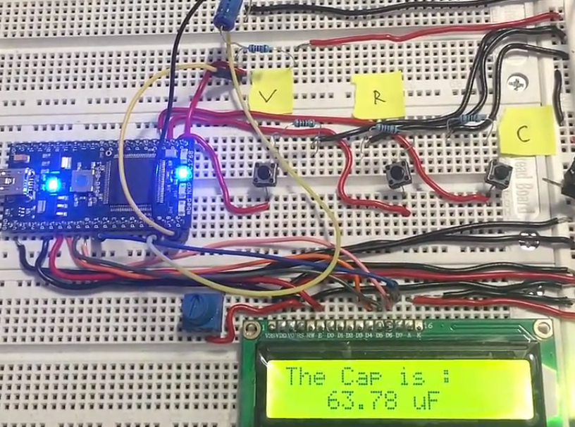
Digital multimeter with microcontroller – Capacitance measurement result


Filed Under: Arduino Projects, Microcontroller Projects


Next Article

← Previous Article
Next Article →

Questions related to this article?
👉Ask and discuss on Electro-Tech-Online.com and EDAboard.com forums.


Tell Us What You Think!! Cancel reply

You must be logged in to post a comment.

EE TECH TOOLBOX

“ee
Tech Toolbox: Internet of Things
Explore practical strategies for minimizing attack surfaces, managing memory efficiently, and securing firmware. Download now to ensure your IoT implementations remain secure, efficient, and future-ready.

EE Learning Center

EE Learning Center
“engineers
EXPAND YOUR KNOWLEDGE AND STAY CONNECTED
Get the latest info on technologies, tools and strategies for EE professionals.

HAVE A QUESTION?

Have a technical question about an article or other engineering questions? Check out our engineering forums EDABoard.com and Electro-Tech-Online.com where you can get those questions asked and answered by your peers!


RSS EDABOARD.com Discussions

  • What is the purpose of the diode from gate to GND in normal Colpitts oscillator Circuits?
  • Antiparallel Schottky Diodes VDI-Load Pull
  • interfacing gsm and gps in proteus
  • 12VAC to 12VDC 5A on 250ft 12AWG
  • My array have wrong radiation pattern

RSS Electro-Tech-Online.com Discussions

  • how to work on pcbs that are thick
  • Actin group needed for effective PCB software tutorials
  • Kawai KDP 80 Electronic Piano Dead
  • Doing consultancy work and the Tax situation?
  • How to repair this plug in connector where wires came loose

Featured – Designing of Audio Amplifiers part 9 series

  • Basics of Audio Amplifier – 1/9
  • Designing 250 Milli Watt Audio Power Amplifier – 2/9
  • Designing 1 Watt Audio Power Amplifier – 3/9
  • Designing a Bass Boost Amplifier – 4/9
  • Designing a 6 Watt Car Audio Amplifier – 5/9
  • Design a low power amplifier for headphones- 6/9

Recent Articles

  • ITG Electronics releases gate drive transformers with 200 – 450 V DC capability
  • Stackpole introduces HCJ jumpers with 70.7 amp continuous current capability
  • Infineon releases MCU with 128K flash and multi-sense capabilities
  • ST introduces 600V GaN gate drivers with 300 ns start-up time
  • ABLIC releases S-19116 automotive voltage detector with 6.8ÎĽs response time

EE ENGINEERING TRAINING DAYS

engineering

Submit a Guest Post

submit a guest post
Engineers Garage
  • Analog IC TIps
  • Connector Tips
  • Battery Power Tips
  • DesignFast
  • EDABoard Forums
  • EE World Online
  • Electro-Tech-Online Forums
  • EV Engineering
  • Microcontroller Tips
  • Power Electronic Tips
  • Sensor Tips
  • Test and Measurement Tips
  • 5G Technology World
  • Subscribe to our newsletter
  • About Us
  • Contact Us
  • Advertise

Copyright © 2025 WTWH Media LLC. All Rights Reserved. The material on this site may not be reproduced, distributed, transmitted, cached or otherwise used, except with the prior written permission of WTWH Media
Privacy Policy

Search Engineers Garage

  • Electronics Projects and Tutorials
    • Electronic Projects
      • Arduino Projects
      • AVR
      • Raspberry pi
      • ESP8266
      • BeagleBone
      • 8051 Microcontroller
      • ARM
      • PIC Microcontroller
      • STM32
    • Tutorials
      • Audio Electronics
      • Battery Management
      • Brainwave
      • Electric Vehicles
      • EMI/EMC/RFI
      • Hardware Filters
      • IoT tutorials
      • Power Tutorials
      • Python
      • Sensors
      • USB
      • VHDL
    • Circuit Design
    • Project Videos
    • Components
  • Articles
    • Tech Articles
    • Insight
    • Invention Stories
    • How to
    • What Is
  • News
    • Electronic Product News
    • Business News
    • Company/Start-up News
    • DIY Reviews
    • Guest Post
  • Forums
    • EDABoard.com
    • Electro-Tech-Online
    • EG Forum Archive
  • DigiKey Store
    • Cables, Wires
    • Connectors, Interconnect
    • Discrete
    • Electromechanical
    • Embedded Computers
    • Enclosures, Hardware, Office
    • Integrated Circuits (ICs)
    • Isolators
    • LED/Optoelectronics
    • Passive
    • Power, Circuit Protection
    • Programmers
    • RF, Wireless
    • Semiconductors
    • Sensors, Transducers
    • Test Products
    • Tools
  • Learn
    • eBooks/Tech Tips
    • Design Guides
    • Learning Center
    • Tech Toolboxes
    • Webinars & Digital Events
  • Resources
    • Digital Issues
    • EE Training Days
    • LEAP Awards
    • Podcasts
    • Webinars / Digital Events
    • White Papers
    • Engineering Diversity & Inclusion
    • DesignFast
  • Guest Post Guidelines
  • Advertise
  • Subscribe