Home appliances have become an integral part of every household. Wireless remote control provides flexibility and ease in accessing these appliances. This has been achieved by interfacing RF module with microcontroller AT89C51. Multiple appliances can be controlled through RF (radio frequency) based wireless remote control.
This remote employs RF transmitter (434 MHz) and works in a way similar to a TV/AC remote. An appliance is turned on when the corresponding switch is pressed the first time. When the same switch is pressed again, it goes off. This on/off state changes every time the switch is pressed. This RF remote is better than IR based TV remotes since RF waves are strong and travel larger distances. Also refer wireless RF remote.
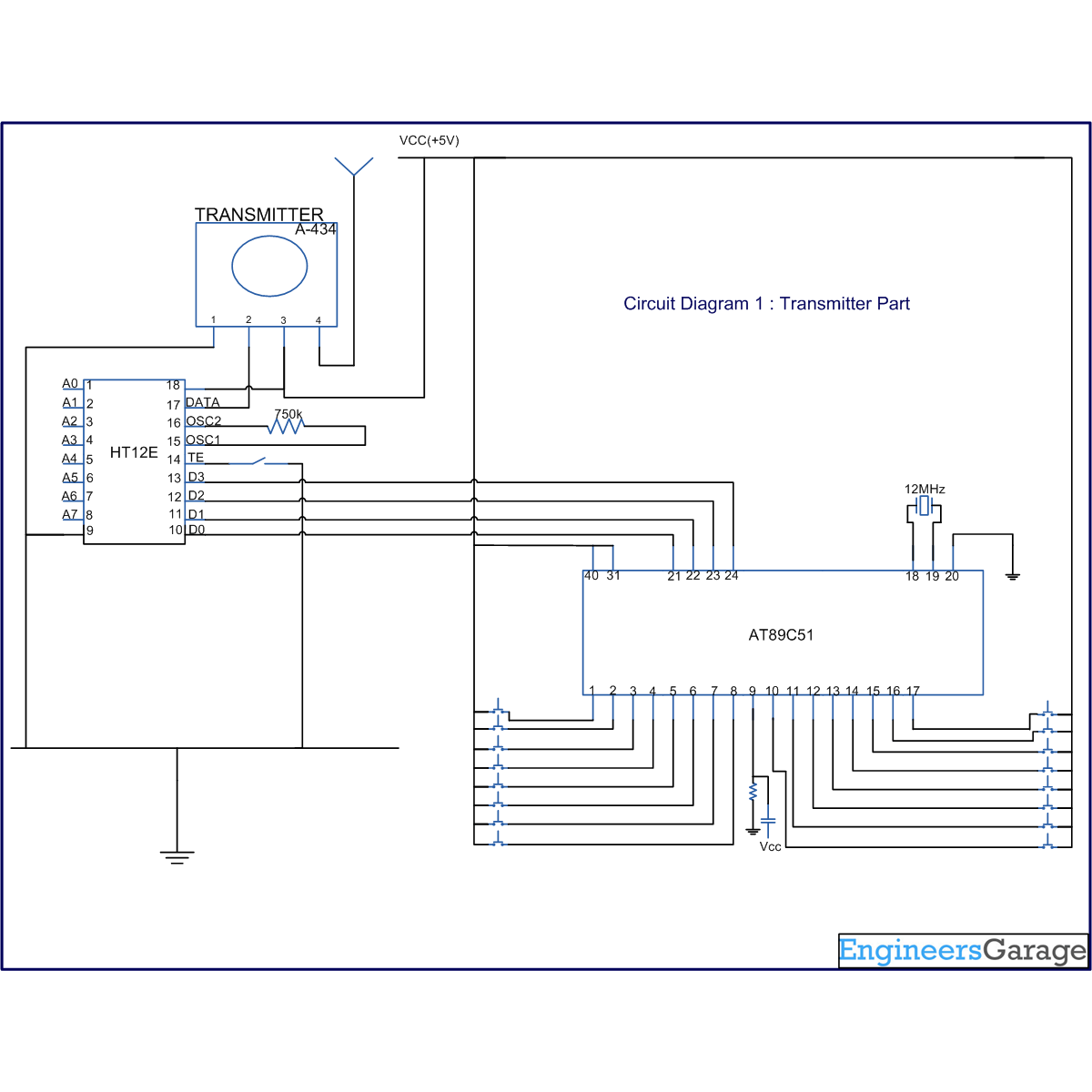
This circuit uses microcontroller AT89C51 and RF module (Tx/Rx pair) to make a wireless remote. For more details on working of RF module, refer wireless RF remote. Here, two microcontrollers have been used, each at transmitter and receiver ends.
The remote consists of 15 tactile switches which are connected to ports P1 and P3 of AT89C51. The microcontroller takes inputs through these switches. Based on these inputs, AT89C51 generates a set of 4 output signals on pins 0-3 of port P2. These pins are connected to data pins of encoder HT12E. These bits, along with address bits, are then converted to serial data. This serial data is sent to transmitter through its data pin. RF transmitter then sends the incoming signals to the receiver, through antenna at a particular baud rate (between 1-10 kbps), at a frequency of 434 MHz.
The serial data received by the receiver is given to decoder IC HT12D. HT12D converts the serial format of signal to original parallel bits. These four parallel lines are connected to pins 0-3 of port P2 of AT89C51. The controller is programmed to switch one or more than one appliance based on the input at pins of port P2.
The RF based remote explained here has several advantages over the conventional IR based remote. Unlike IR, user does not need to direct the RF remote to the receiver module. Also it provides a long range access as compared to IR. With RF, many receivers can be controlled by a single transmitter if the address bits are properly configured.
Project Source Code
###
//Program for Transmitter Part #include<reg51.h> sbit in1=P1^0; //input pins at port P1 sbit in2=P1^1; sbit in3=P1^2; sbit in4=P1^3; sbit in5=P1^4; sbit in6=P1^5; sbit in7=P1^6; sbit in8=P1^7; sbit in9=P3^0; //input pins at port P3 sbit in10=P3^1; sbit in11=P3^2; sbit in12=P3^3; sbit in13=P3^4; sbit in14=P3^5; sbit in15=P3^6; sbit out1=P2^0; //output pins at port P2 sbit out2=P2^1; sbit out3=P2^2; sbit out4=P2^3; unsigned int i,j; void delay(unsigned int time) { for(i=1;i<time;i++) for(j=1;j<1275;j++); } void _default() { out1=1; out2=1; out3=1; out4=1; } void main(void) { in1=in2=in3=in4=in5=in6=in7=in8=in9=in10=in11=in12=in13=in14=in15=1; //configning as input port in1=in2=in3=in4=in5=in6=in7=in8=in9=in10=in11=in12=in13=in14=in15=0; //lowering the input bits while(1) { in1=in2=in3=in4=in5=in6=in7=in8=in9=in10=in11=in12=in13=in14=in15=0; if(in1==1) { out1=1; out2=1; out3=1; out4=0; delay(50); _default(); } if(in2==1) { out1=1; out2=1; out3=0; out4=1; delay(50); _default(); } if(in3==1) { out1=1; out2=1; out3=0; out4=0; delay(50); _default(); } if(in4==1) { out1=1; out2=0; out3=1; out4=1; delay(50); _default(); } if(in5==1) { out1=1; out2=0; out3=1; out4=0; delay(50); _default(); } if(in6==1) { out1=1; out2=0; out3=0; out4=1; delay(50); _default(); } if(in7==1) { out1=1; out2=0; out3=0; out4=0; delay(50); _default(); } if(in8==1) { out1=0; out2=1; out3=0; out4=1; delay(50); _default(); } if(in9==1) { out1=0; out2=1; out3=0; out4=0; delay(50); _default(); } if(in10==1) { out1=0; out2=1; out3=1; out4=1; delay(50); _default(); } if(in11==1) { out1=0; out2=1; out3=1; out4=0; delay(50); _default(); } if(in12==1) { out1=0; out2=0; out3=1; out4=1; delay(50); _default(); } if(in13==1) { out1=0; out2=0; out3=1; out4=0; delay(50); _default(); } if(in14==1) { out1=0; out2=0; out3=0; out4=1; delay(50); _default(); } if(in15==1) { out1=0; out2=0; out3=0; out4=0; delay(50); _default(); } } }//Program for Receiver Part #include<reg51.h> sbit in1=P2^0; //input pins at port P2 sbit in2=P2^1; sbit in3=P2^2; sbit in4=P2^3; sbit out1=P1^0; //output pins at port P1 sbit out2=P1^1; sbit out3=P1^2; sbit out4=P1^3; sbit out5=P1^4; sbit out6=P1^5; sbit out7=P1^6; sbit out8=P1^7; sbit out9=P3^0; //output pins at port P3 sbit out10=P3^1; sbit out11=P3^2; sbit out12=P3^3; sbit out13=P3^4; sbit out14=P3^5; sbit out15=P3^6; sbit led=P2^7; //LED to test initial condition unsigned int a,b,c,d,e,f,g,h,i,j,k,l,m,n,o,p,q,r,s; void main() { in1=in2=in3=in4=1; //configning as input port out1=out2=out3=out4=out5=out6=out7=out8=out9=out10=out11=out12=out13=out14=out15=1; a=b=c=d=e=f=g=h=i=j=k=l=m=n=o=0; while(1) { p=in1; q=in2; r=in3; s=in4; led=1; if(p==1&&q==1&&r==1&&s==1&&out1==1&&out2==1&&out3==1&&out4==1&&out5==1&&out6==1&&out7==1&&out8==1&&out9==1&&out10==1&&out11==1&&out12==1&&out13==1&&out14==1&&out15==1) { led=0; } if(p==1&&q==1&&r==1&&s==0) { a=a+1; } out1=1-a%2; if(p==1&&q==1&&r==0&&s==1) { b=b+1; } out2=1-b%2; if(p==1&&q==1&&r==0&&s==0) { c=c+1; } out3=1-c%2; if(p==1&&q==0&&r==1&&s==1) { d=d+1; } out4=1-d%2; if(p==1&&q==0&&r==1&&s==0) { e=e+1; } out5=1-e%2; if(p==1&&q==0&&r==0&&s==1) { f=f+1; } out6=1-f%2; if(p==1&&q==0&&r==0&&s==0) { g=g+1; } out7=1-g%2; if(p==0&&q==1&&r==0&&s==1) { h=h+1; } out8=1-h%2; if(p==0&&q==1&&r==0&&s==0) { i=i+1; } out9=1-i%2; if(p==0&&q==1&&r==1&&s==1) { j=j+1; } out10=1-j%2; if(p==0&&q==1&&r==1&&s==0) { k=k+1; } out11=1-k%2; if(p==0&&q==0&&r==1&&s==1) { l=l+1; } out12=1-l%2; if(p==0&&q==0&&r==1&&s==0) { m=m+1; } out13=1-m%2; if(p==0&&q==0&&r==0&&s==1) { n=n+1; } out14=1-n%2; if(p==0&&q==0&&r==0&&s==0) { o=o+1; } out15=1-o%2; } }###
Circuit Diagrams
Project Components
Filed Under: 8051 Microcontroller.


Questions related to this article?
👉Ask and discuss on EDAboard.com and Electro-Tech-Online.com forums.
Tell Us What You Think!!
You must be logged in to post a comment.