The Raspberry pi is a device which uses the Broadcom controller chip which is a SoC (System on Chip). This SoC has the powerful ARM11 processor which runs on 700 MHz at its core. This powerful processor and the controller having the peripherals like timers, interrupt controller, GPIO, PCM / I2S, DMA controller, I2C, SPI slave, PWM, UART, USB, graphical processing unit (GPU) which includes VideoCore, MPEG-2 and MPEG-4 and a 512 MB SDRAM makes it a mini-computer.
The board is provided with a RCA connector which can be used to connect it directly to a TV screen which is based on PAL and NTSC standard. The board also has a HDMI connector output which can be used to connect the board to a HD TV. There is an Ethernet port which can be used to connect the board to a computer network. Those who don’t want to use a HDTV and separate keyboard and mouse for the Rspberrypi board can plug the board using a LAN cable to the Ethernet port of the PC and do remote access in TUI or GUI mode.
The operating systems like Archlinux ARM, OpenELEC, Pidora, Raspbmc, RISC OS and the Raspbian and also Ubuntu versions are available for the Raspberrypi board. Linux operating systems especially Ubuntu is preferred for all kind of programming and development. The immediate advantage of having an Operating System like Ubuntu running on an embedded system device is multitasking. All Linux OS provides Multi-user Multitasking feature. This article discusses how to perform single user multitasking in a Raspberrypi board by executing a single C code rather than executing different codes one after the another as background processes, or using a Shell script.
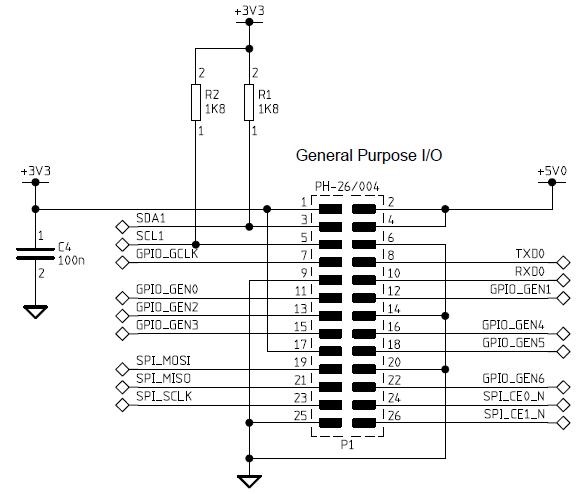
In this project the Raspberrypi board is loaded with Ubuntu and is remotely accessed using VNC. The Raspberrypi board is also connected to the internet. There are 26 connectors which can be taken out from the connector port of the Raspberrypi board. All the connector pins are taken out using 13*2 pin female connectors and at the other end of their wire 26 pin Burg stick male connectors are attached. The Burg stick male connectors allow each pin out from the Raspberrypi board to be plugged into the holes of a breadboard. To access the pins that coming out of the Broadcom controller of the Raspberrypi board using C language, a C library is available called “bcm2835” which has been downloaded and installed.
The Operating system running on the 700Mz processor is powerful enough to do multitasking and hence it can run so many processes in parallel just like the Desktop OS can do. The user can write so many codes and made them executable and then run each of them as background processes to achieve multi-tasking. The another easy method to achieve the multitasking is using a Shell script in which all the commands to execute the codes as background process are scripted into, but it is not a proper method since the user can have little control over the processes which are initiated by the Shell script. The same thing can be done by executing a single C code also and the technique is discusses in the following section.
There are eight general purpose IO pins on the 13*2 pin connectors of the Raspberrypi board and to each one of them a LED is connected through 1K resistor. Separate code has been written to blink the LEDs individually and made them into executable files named blink2, blink3, blink4, blink5, blink6, blink7 and blink8. It is suggested to keep all the .c files and the executable files in a single folder for this particular project.
The user can run any of the LED blinking programs from the command line. For example to execute the file ‘blink1’, the user can use the following command:
./blink1
The user can perform multi-tasking on them by entering the following commands one after the other. The user can perform multi-tasking with the eight LED codes by entering the following eight commands one after the other.
./blink1 &
./blink2 &
./blink3 &
./blink4 &
./blink5 &
./blink6 &
./blink7 &
./blink8 &
The easiest method of executing them using a single C file, where the commands for executing the executable file are done using the ‘system ()’ function.
system ()
The ‘system ()’ is a function which can be called from any C program with arguments as the commands need to be executed by the Shell. The commands can be passed to the function in the form of a string and it will pass the string to the Shell which will execute the commands.
To execute the file “blink1” using the system () function the user can simply pass the required command to the system () function as given in the following.
system ( “blink1” );
For execute the LED blinking codes as background process, simply open up a new .c file in vim editor and write down the following simple code;
#include <unistd.h>
int main ()
{
system ( “./blink1 &” );
system ( “./blink2 &” );
system ( “./blink3 &” );
system ( “./blink4 &” );
system ( “./blink5 &” );
system ( “./blink6 &” );
system ( “./blink7 &” );
system ( “./blink8 &” );
return 0;
}
Save this file with a name, say “system_blink_all.c” and then compile them into an executable file “system_blink_all”.
To execute the code in which the commands for multitasking are passed to the Shell using ‘system()’, use the following command;
./system_blink_all
*** Make sure that all the executable files blink1, blink2 etc. are there in the same folder with the executable file “system_blink_all”.
***Note that in this project the latest version of library “bcm2835” is used with an old version of Raspberrypi board. It is not possible to access the pin number 13 of the old board with the latest library version and hence in the code “blink3.c” the pin number 24 is used to blink the 3rd LED. The circuit diagram is also drawn accordingly. Those who have the latest version of the board can use the pin 13 without any trouble.
To find the ‘Revision’ and other important details about the Raspberrypi board, use the following command;
cat /proc/cpuinfo
Circuit Diagrams

Project Components
Project Video
Filed Under: Raspberry pi
Filed Under: Raspberry pi

Questions related to this article?
👉Ask and discuss on EDAboard.com and Electro-Tech-Online.com forums.
Tell Us What You Think!!
You must be logged in to post a comment.