Power constraint is a critical consideration undertaken by designers when selecting a microcontroller for an application — particularly with IoT applications where power plays a vital role. IoT nodes are only useful in the field if they last for years or even a decade on a single battery.
The race for lower power devices between semiconductor manufactures is high, and every manufacturer has a dedicated line of SOC/MPU/MCU’s, which are categorized as low- or ultra-low power.
ATTINY 8-bit microcontroller series by ATMEL (now Microchip Technology) was considered to be the king of hibernation a decade ago. The fact that an ATTINY consumes 0.2µA in deep sleep mode earned them respect from engineers and became the top priority of designers for low power applications.
Today, ATtiny is incorporated various other microcontroller chips because of its rapid development in semiconductor scaling and power management benefits. However, due to diversity in applications and user requirements even in sleep mode (RTC, DMA, DAC active, etc.), it’s hard to develop consensus on who is pioneering the low power race.
In recent decades, 32-bit microcontrollers gained popularity. 8-bit microcontrollers mostly are 5 volts tolerant, whereas 32-bit microcontrollers stand at 3.3 volts. This power difference with compact design and more general-purpose input/output pins resulted in a sizeable market share for 32-bit MCU’s. Not only do 32-bit microcontrollers consume low power, but they offer other peripherals and protocols in a single chip.
In this tutorial, I will discuss and measure the power consumption of STM32F0xx 32-bit series microcontrollers offered by STMicroelectronics.
Stm32f0xx has three types of low power modes.
- Stop Mode
- Sleep Mode
- Standby Mode
Stop mode features
In stop mode, the real-time clock is powered by LSI (low speed internal) clock source. HIS (High speed internal) and HSE (External) clock buses are turned off. The power regulator is in low power mode. The regulator in low power mode means flash is also in power-down mode. In stop mode, all clocks are stopped except the one connected to RTC. Exiting from stop mode is possible with real-time clock interrupt or any other global interrupt.
Sleep mode features
In sleep mode, the CPU of the processor goes to power-down mode. All the peripherals in the MCU are awake and running. For exiting from sleep mode, any global interrupt can be utilized, or any event(external/internal) can bring out the device from sleep to awake state.
Power can also be saved by disabling the peripherals and GPIO pins before going in the stop or sleep mode. This prevents any leakage current from draining out the battery.
Standby mode
In standby mode, all the clocks are stopped, and static RAM loses all its content. Only the RTC clock is active. Exiting from stand by mode starts the booting process, similar to resetting the MCU. The only difference is, with standby reset, RTC register contents are not lost, and RTC maintains data. Exiting from standby mode is possible with an external event on some dedicated MCU pins, or RTC alarm can bring the MCU out of standby mode.
Comparing the results
Ideal State
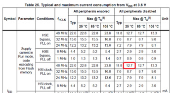
According to datasheet, STM32 consumes 12.7 mA of current during ideal conditions in run mode.
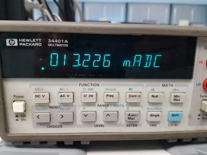
 In my program code, I disabled all peripherals, made all GPIO’s analog to reduce any leakage, and save as much power as I can. Using an ammeter, the current consumption by MCU in run mode is recorded at 13.26 mA.
Sleep Mode State
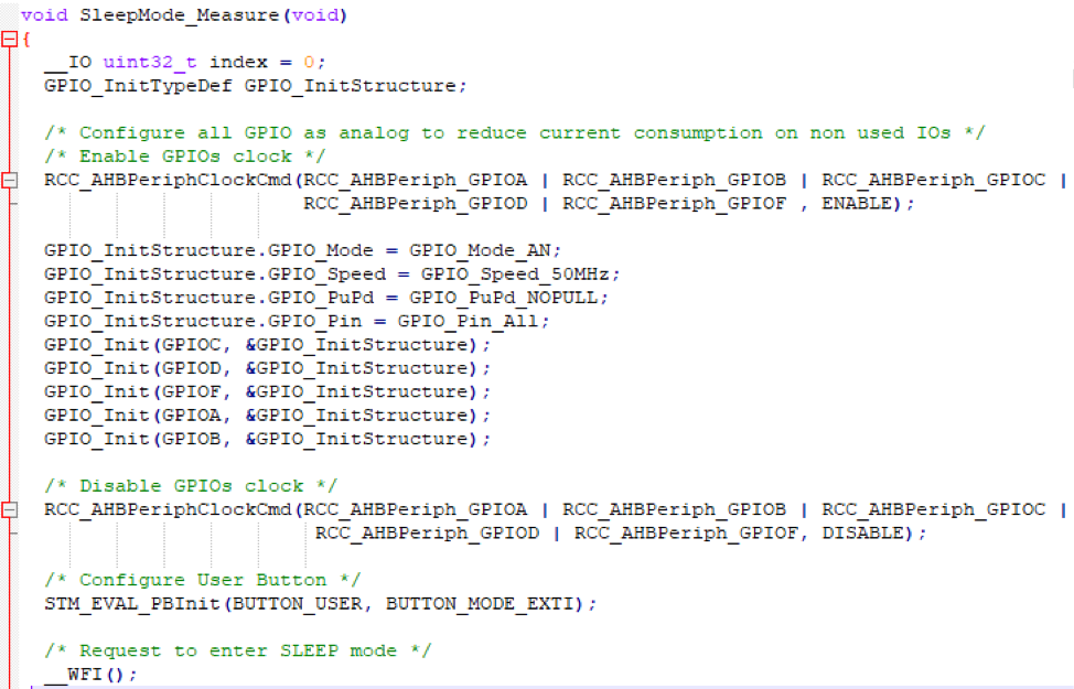
The sleep mode code snap shoot is below. I enter the sleep mode by configuring all GPIOS as analog and disabling the GPIO’s clocks. Exiting from sleep mode is on EXTI external interrupt. push-button is mapped to EXTI pin.
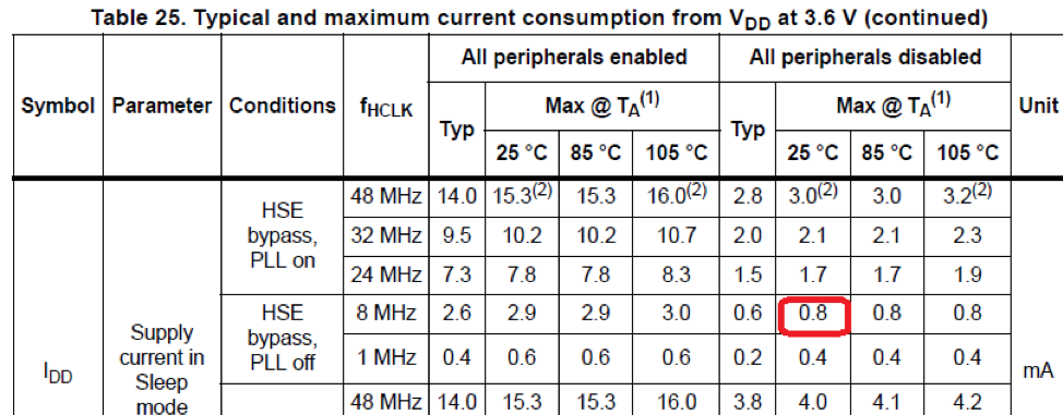
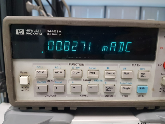
According to datasheet, current consumption in sleep, state is 0.8mA.
Measuring the current consumption in sleep state, an ammeter shows 0.82mA.
Standby and stop modes
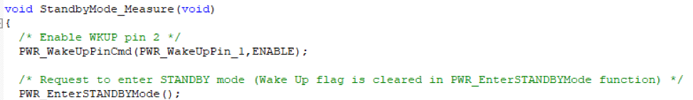
The easiest low power state in which MCU can enter is standby. Just one bit of a global power register is required to be set for entering into the standby mode. Before entering the standby mode, we must define the exit pin/protocol from standby mode. The code below is invoking the standby mode for stm32f051 microcontroller.
Stop mode requires plenty of registers to be updated for entering in it. Exiting from stop mode also requires many registers to be manipulated. To see the stop mode code, download the project code.
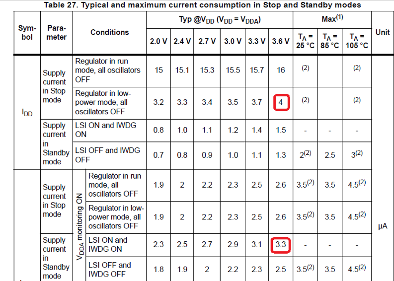
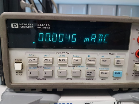
According to the data sheet in stop mode, 4uA of current is consumed, and standby consumes 3.3uA of current.
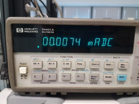
On the ammeter current consumption in stop mode is recorded as 7.4uA, and in standby mode, it is 4.6uA.
Exiting from all the low power states requires some bits/flags to be cleared. External and internal interrupts play a vital role in exiting from low power states. Peripheral interrupts, especially the real-time clock, need to be mastered to wake up from low power states.
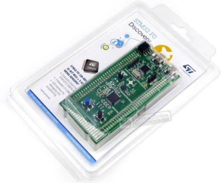
I used the STM32F0 discovery development board to test the low power states.
I defined everything in the project code. On startup, the LEDs on the board blinks, and then MCU enters in the stop mode. RTC (real-time clock) interrupt is utilized to wake up from stop mode. RTC is programmed for 5 seconds. After 5 seconds, the MCU will exit from the stop mode.
Upon exiting from the stop mode led’s again blink, and after few blinks, MCU enters in sleep mode. To wake up from sleep mode, press the push button on the board. Again, upon exiting from sleep mode led’s blink, and finally, the MCU goes in standby mode. To exit from standby, press the pushbutton. Standby resets the MCU and execution starts from the beginning.
The project code is written and compiled in Keil uVision ide. You can Download Code.
Where can you buy parts?
STM32f0 discovery
You may also like:


Filed Under: Electronic Projects, STM32.

Questions related to this article?
👉Ask and discuss on Electro-Tech-Online.com and EDAboard.com forums.
Tell Us What You Think!!
You must be logged in to post a comment.