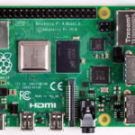
Raspberry Pi is the most popular single-board computer. As an embedded microcomputer, data acquisition is almost essential in Raspberry Pi. Though Pi has several GPIO (General Purpose Input/Output) pins, it does not have any built-in or onboard analog-to-digital converter. Therefore, Pi on its own cannot sample data from analog sensors. In embedded applications, analog sensors are frequently used. In fact, many sensors like light-dependent resistors (LDRs) and IR sensors are just not available in any digital form. In this case, analog sensors can be interfaced with Raspberry Pi using two ways. One is to use an external analog-to-digital converter; the second is to sample data from analog sensors using a microcontroller and transfer all captured data to Raspberry Pi via a serial interface.
Interfacing Raspberry Pi with a microcontroller only to fetch analog data is not a viable solution. An external ADC is the best solution when Raspberry Pi operates as a standalone embedded microcomputer, and analog data acquisition is needed.
Analog data acquisition on Raspberry Pi has several benefits. It is much easier to apply machine learning algorithms and deep learning models in a microcomputer like Raspberry Pi than any microcontroller. Microcontrollers are too resource constraint and have limited software tools and APIs to apply machine learning algorithms or implement deep learning networks. The available software tools of machine learning and deep learning for microcontrollers are also limited in their capabilities. For example, computer vision applications usually require large RAM and efficient camera sensors for any practical application. The machine learning tools for microcontrollers are not much performant for such resource-intensive embedded applications.
This project will explore how to perform analog data acquisition in Raspberry Pi using ADS1115 or ADS1015 ADC chips. In the same context, we will also discuss how we can read analog data from IR sensors on Raspberry Pi for obstacle detection in a Raspberry Pi robot.
Components required
- Raspberry Pi 3B/4B x1
- ADS1115/ADS1015 ADC x1
- IR sensors x1
- Breadboard x1
- Connecting wires/Jumper wires
ADS1115/ADS1015 Pi Vs. microcontrollers
As already discussed, we have two ways to sample analog data in Raspberry Pi. Before discussing the use of external ADCs like ADS1115/ADS1015, it is worth noting the difference between both approaches. When we interface a microcontroller like an Arduino board with Raspberry Pi, we interface a completely separate embedded solution with the microcomputer. If the Arduino board operates on a different voltage level like most of the Arduino boards are 5V circuits, we cautiously need to use a TTL logic level converter between the microcontroller and the Raspberry Pi. Otherwise, we will damage the entire Pi, or at least the board pins. In the case of external ADC, we can drive the ADC from the Raspberry Pi voltage outputs.
A microcontroller will run independently with its data sampling cycle. In this case, a Python script on Raspberry Pi will need to catch up with the sampling speed of the microcontroller. This also means that data acquisition control remains with the microcontroller and not the Raspberry Pi. This is sometimes useful when implementing time-critical applications where the sensor data must be immediately processed for a quick response. In the case of an ADC, the data acquisition and sampling rate are controlled by the Raspberry Pi. Some developers feel that Raspberry Pi is running a normal operating system can be lagging in the acquisition and processing of analog data with external ADCs as other processes can override currently running Python scripts. However, this problem can be easily solved by delegating the analog data sensing in a parallel thread by employing multi-threading.
A microcontroller must only be used with Raspberry Pi when several time-critical embedded tasks need to be performed in parallel. The Raspberry Pi, in this case, can be deployed in the backend for performing extensive data analytics, implementing machine learning or deep learning models on sensor data, managing communication with a cloud platform, and managing IoT (Internet of Things) operations.
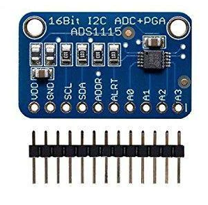
ADS115/ADS1015 ADC
ADS1015 and ADS1115 are low-power, high-precision analog-to-digital converters. These are widely used with Raspberry Pi as these chips also operate at a voltage of 3V3. ADS1015 is a 12-bit ADC with four analog input channels. ADS1115 is a 16-bit ADC with four analog input channels.
In this project, we will be using ADS1115. ADS1115 supports two types of data acquisition – single-ended and differential. In single-ended conversion, analog data from each of the four analog input pins are independently sampled. The difference between the voltages at two analog input pins is sampled in a differential mode of operation. ADS1115 has a resolution of 16 bits, of which one bit remains reserved for plus/minus sign of the voltage difference in differential mode, and the remaining 15 bits are used for storing converted voltage values. The chip has an I2C interface for serial data communication with a microcomputer/microcontroller.
The sampling rate in ADS1115 can be set anywhere between 8 and 860 samples per second. Higher is the sampling rate; less is the time taken by ADC to capture and convert the analog signal. The chip also has a built-in gain amplifier, amplifying weak voltage signals 2-3x to 16x times. The conversion (single-ended or differential) can be done in two ways. The conversion is initiated by the Raspberry Pi (or controlling microcomputer/microcontroller) in one method. The converted value is stored in a register on ADS1115. The Raspberry Pi then reads the register. In the second method, conversion is done by the ADS1115 continuously. The signal is sampled at a preprogrammed rate (8~860 sps), and the converted value is repeatedly updated in a register on the ADS1115. The Raspberry Pi must repeatedly read the ADS1115 register according to the programmed sampling rate. If Raspberry Pi reads the register at a lower rate, it misses several captured samples. On the other hand, if Raspberry Pi reads the register at a higher rate, it logs several redundant values for the same samples.
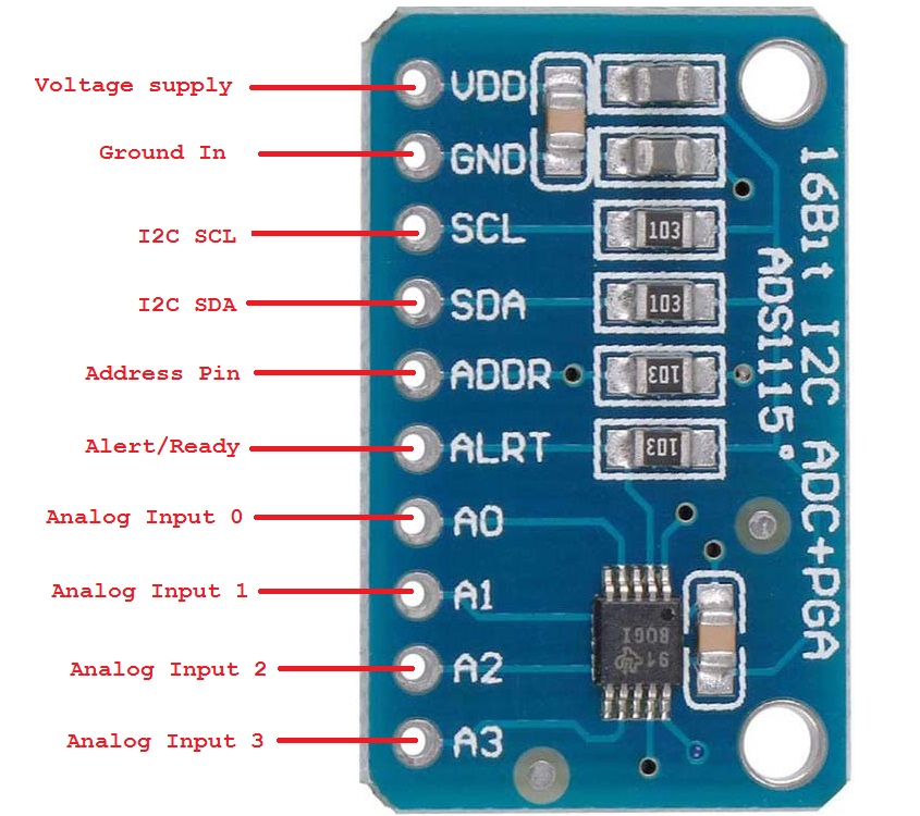
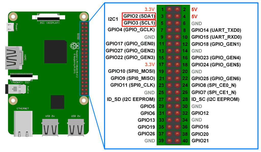
ADS1115 has the following pin diagram.
Wiring ADS115/ADS1015 with Raspberry Pi
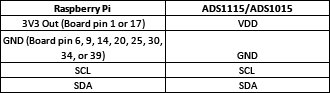
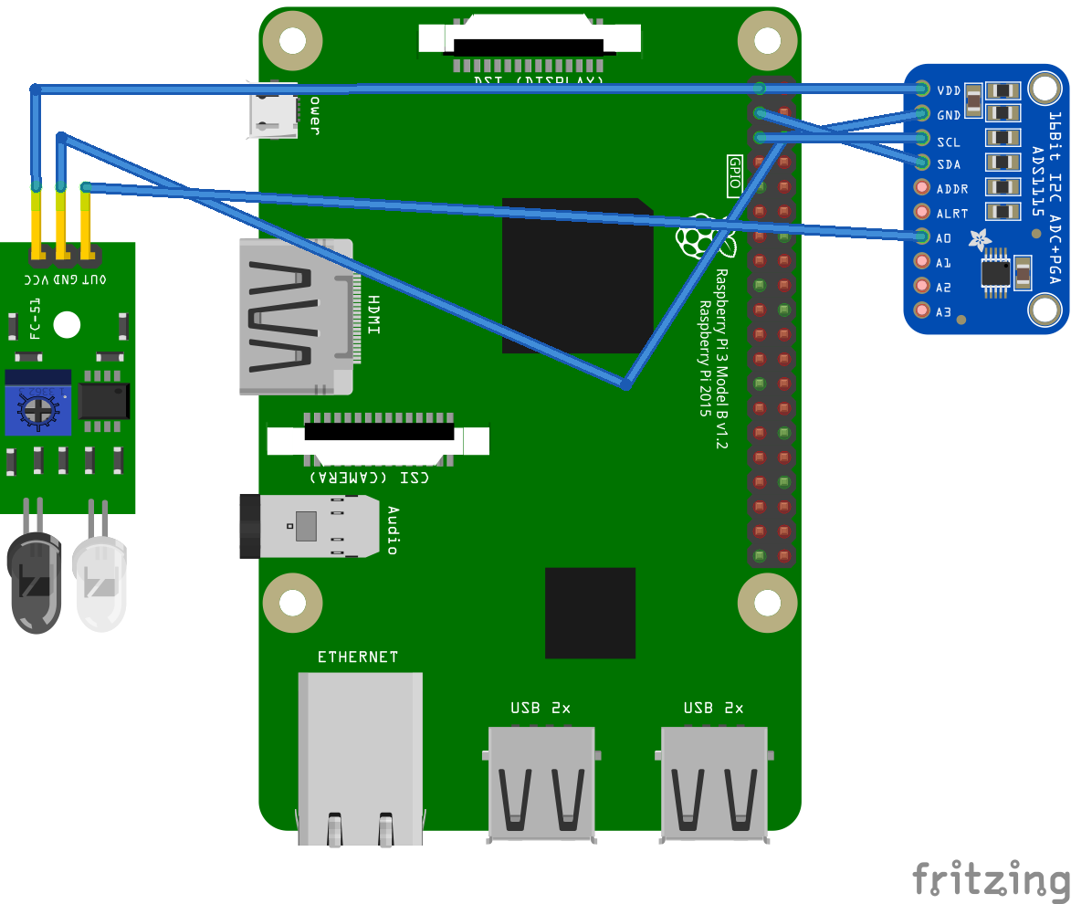
ADS1115 and ADS1015 sample analog data from sensors and transfer the converted values to Raspberry Pi over the I2C interface. Both chips use the same I2C protocol and have the same pin configuration. For connecting ADS1015/ADS1115, follow the circuit connections summarized in the table below.
Enabling I2C on Raspberry PiThe analog output of a sensor must be connected to A0, A1, A2, or A3 of the ADS1015/ADS1115. Maximum four sensors can be connected to the ADS1015/ADS1115. The sensor can be supplied voltage from the Raspberry Pi itself. If an external supply powers the sensor, it must not be over 3.3V.
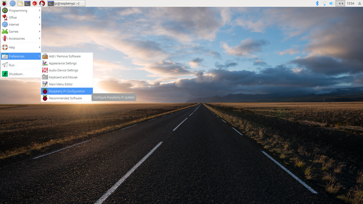
ADS1015 and ADS1115 communicate with Raspberry Pi over the I2C protocol. Before we interface ADS1015/ADS1115 with Raspberry Pi, the I2C port must be enabled on the microcomputer. For this, navigate to Preferences -> Raspberry Pi Configuration.
 A configuration window will open, as shown below.
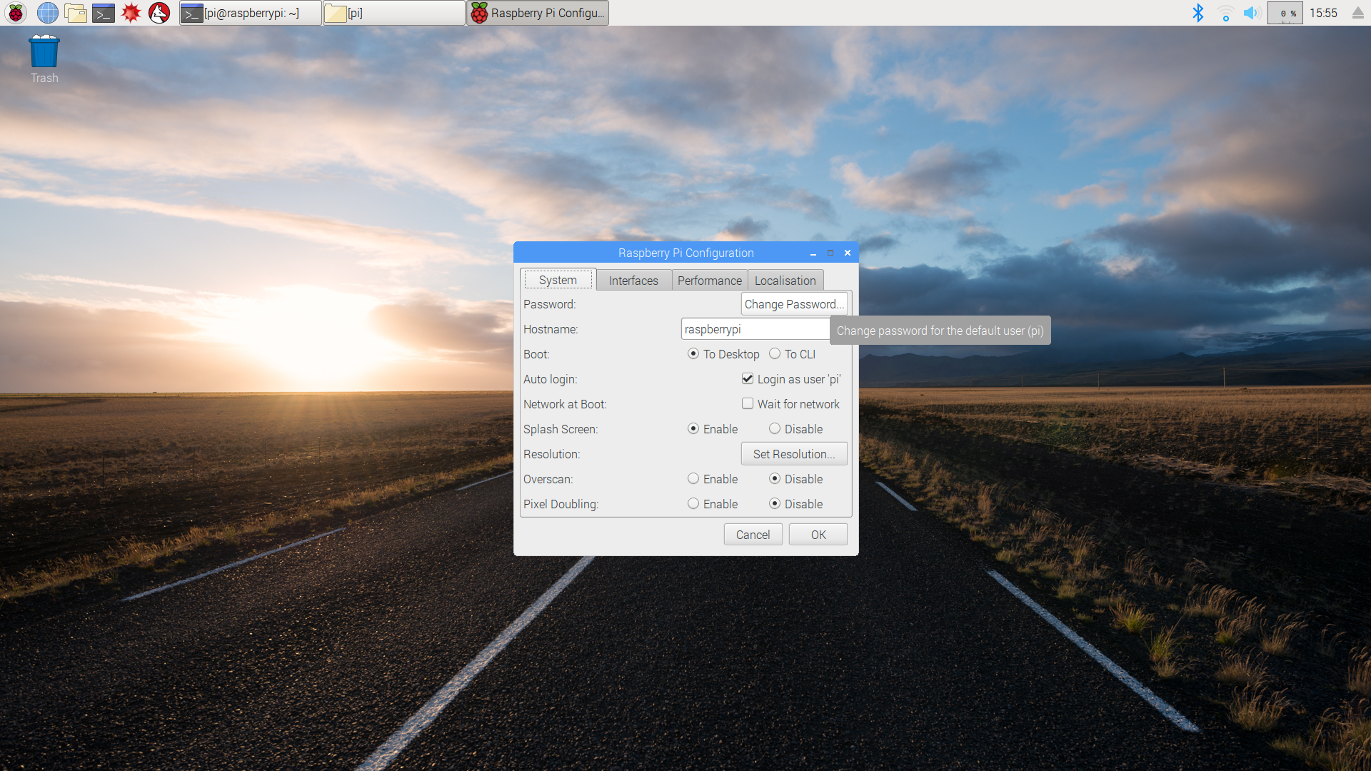
Select the Interfaces tab. Enable I2C and click ok.
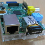
 That’s It. Now Raspberry Pi can communicate over an I2C port. The I2C port in Raspberry Pi is shown in the image below.
 To learn more about I2C communication in Raspberry Pi. You may also be interested in how the I2C protocol works.
Adafruit ADS1x15 Raspberry Pi python library
Fortunately, we have Adafruit ADS1x15 Python Library available to work with ADS1015 and ADS1115. We do not need to write any Python script from scratch to interface ADS1015/ADS1115 with Raspberry Pi.
Installing ADS1x15 python library in Raspberry Pi
The Adafruit ADS1x15 Python library can be installed in Raspberry Pi manually or via the PiP package manager. For installing the library from source, open Bash Terminal by navigating Accessories->Terminal or simply clicking on the Terminal icon; then execute the following commands.
sudo apt-get update
sudo apt-get install build-essential python-dev python-smbus git
cd ~
git clone https://github.com/adafruit/Adafruit_Python_ADS1x15.git
cd Adafruit_Python_ADS1x15
sudo python setup.py install
For installing the library using the PiP package manager, open Bash Terminal by navigating Accessories->Terminal or simply clicking on the Terminal icon; then execute the following commands.
sudo apt-get update
sudo apt-get install build-essential python-dev python-smbus python-pip
sudo pip install adafruit_ads1x15
If you are using Python3, you need to install the library using pip3 as follows.
sudo pip3 install adafruit_ads1x15
Once the library is successfully installed in your Python installation, you can use it by simply importing the library in a script.
Python code for analog data acquisition using ADS1115/ADS1015
For using the Adafruit ADS1x15 library in a python script, import the library using the following statement.
import Adafruit_ADS1x15
Then, you need to instantiate an object of the Adafruit_ADS1x15 class using the following statement. The instance is named ‘adc’ here; it can be any identifier.
adc = Adafruit_ADS1x15.ADS1115()
Next, you need to set the gain for the built-in amplifier. The gain needs to be set according to the Programmable Amplifier Gain table provided in the ADS1015/ADS1115 datasheet. A quick reference of the amplifier gain and the desired sensing voltage range is summarized in the table below.
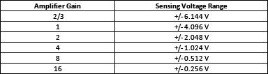
The gain can be set using the following statement.
GAIN = 1
The converted voltage reading ranges from -32768 to +32767 for ADS1115 and -2048 to +2047 for ADS1015. A value of 0 references to the ground level. The actual voltage sensed is determined by the proportionality of the voltage range set by the amplifier gain. For example, if the gain is set to 1, the value of 32767 refers to a voltage of 4.096V in ADS1115. Any value in the range from -32768~32767 refers to an analog voltage (4.096/32767)*a. The analog reading from analog input A0 of ADS1115/ADS1015 can be read using the following statement.
value = adc.read_adc(0, gain=GAIN)
Similarly, analog readings from analog inputs A1~A3 of ADS1015/ADS1115 can be read using the following statements.
value = adc.read_adc(1, gain=GAIN)
value = adc.read_adc(2, gain=GAIN)
value = adc.read_adc(3, gain=GAIN)
Here, ‘value’ is a variable in Python script. The ADC readings can be fetched in a loop if multiple analog sensors are interfaced with Raspberry Pi via ADS1015/ADS1115. The actual voltages can be calculated using the equation stated above. Following is an example of deriving actual voltage reading.
GAIN = 1
value = adc.read_adc(0, gain=GAIN)
analog_voltage = value*(4.096/32767)
Interfacing IR sensors with Raspberry Pi via ADS1115/ADS1015
IR sensors are commonly used sensors that are available in only analog form. The IR sensors are widely used in Raspberry Pi Robots for line following or obstacle detection. IR sensors can be easily interfaced with Raspberry Pi via ADS1015/ADS1115. IR sensor has three pins – VDD, GND, and Out. Connect the Out pin of the IR sensor with any analog input pin of the ADS1015/ADS1115 and supply the positive and negative supply to the sensor from the Raspberry Pi itself. Then, interface the ADS1015/ADS1115 with Raspberry Pi as mentioned above. This way, an IR sensor, an analog sensor is now interfaced to Raspberry Pi.
Python script to read IR sensor output in Raspberry Pi
Execute the following script to fetch analog readings from the IR sensor in Python console.
import time
import Adafruit_ADS1x15
adc = Adafruit_ADS1x15.ADS1115()
# Choose a gain of 1 for reading voltages from 0 to 4.09V.
# Or pick a different gain to change the range of voltages that are read:
# – 2/3 = +/-6.144V
# – 1 = +/-4.096V
# – 2 = +/-2.048V
# – 4 = +/-1.024V
# – 8 = +/-0.512V
# – 16 = +/-0.256V
# See table 3 in the ADS1015/ADS1115 datasheet for more info on gain.
GAIN = 1
while True:
value = adc.read_adc(0, gain=GAIN)
print(value)
time.sleep(0.5)
Results
The IR sensor outputs a higher voltage when there is no obstacle in its path. When the sensor faces an obstacle, its output is reduced. The ADC reading when there is no obstacle in the path of the IR sensor is found to be 24550~24729. With an amplifier gain of 1, these readings correspond to a voltage of 3.06~3.09V. The ADC reading when an obstacle blocks the IR sensor is 660~670. With an amplifier gain of 1, these readings correspond to a voltage of 0.081~0.083V. It should be noted the output of the IR sensor depends upon its calibration by the onboard pot.
Conclusion
ADS1015 and ADS1115 are low-power high, resolution analog to digital converters. These can be easily interfaced with Raspberry Pi and communicated via the I2C protocol. These ICs can sense a maximum of four analog voltages simultaneously in a single-ended configuration. Therefore, making ADS1015 and ADS1115 the best ADCs for Raspberry Pi robots.
You may also like:

Filed Under: Electronic Projects, Featured, Sensors, Tutorials, Video

Questions related to this article?
👉Ask and discuss on EDAboard.com and Electro-Tech-Online.com forums.
Tell Us What You Think!!
You must be logged in to post a comment.