Summary:
This is the project used to identify and measure unknown resistance or capacitance. When we connect any resistor or capacitor in the breadboard circuit will find whether it is a resistor or capacitor and calculate the exact value of the resistance or capacitance and it is displayed in the 16×2 LCD. This is done by utilizing the ADC feature of the Arduino and the Auto ranging voltage divider concept to measure the resistance with reduced errors and RC charging circuit to develop the Capacitance meter. Now-a-days we use multimeter with range selector switches to find the unknown resistance which will consume time, so we also introduced Auto ranging feature to reduce the manual ranging functions by implementing logics in coding and hardware which is discussed below.
Description:
Hardware assembly:
The entire project can be divided into three basic blocks;
-
Auto ranging Resistance Sensor Unit
-
RC Charging circuit
-
Isolating Circuit
-
Processor Unit
-
Display Unit

Fig. 1: Block Diagram of Arduino Based Resistance Capacitance Meter
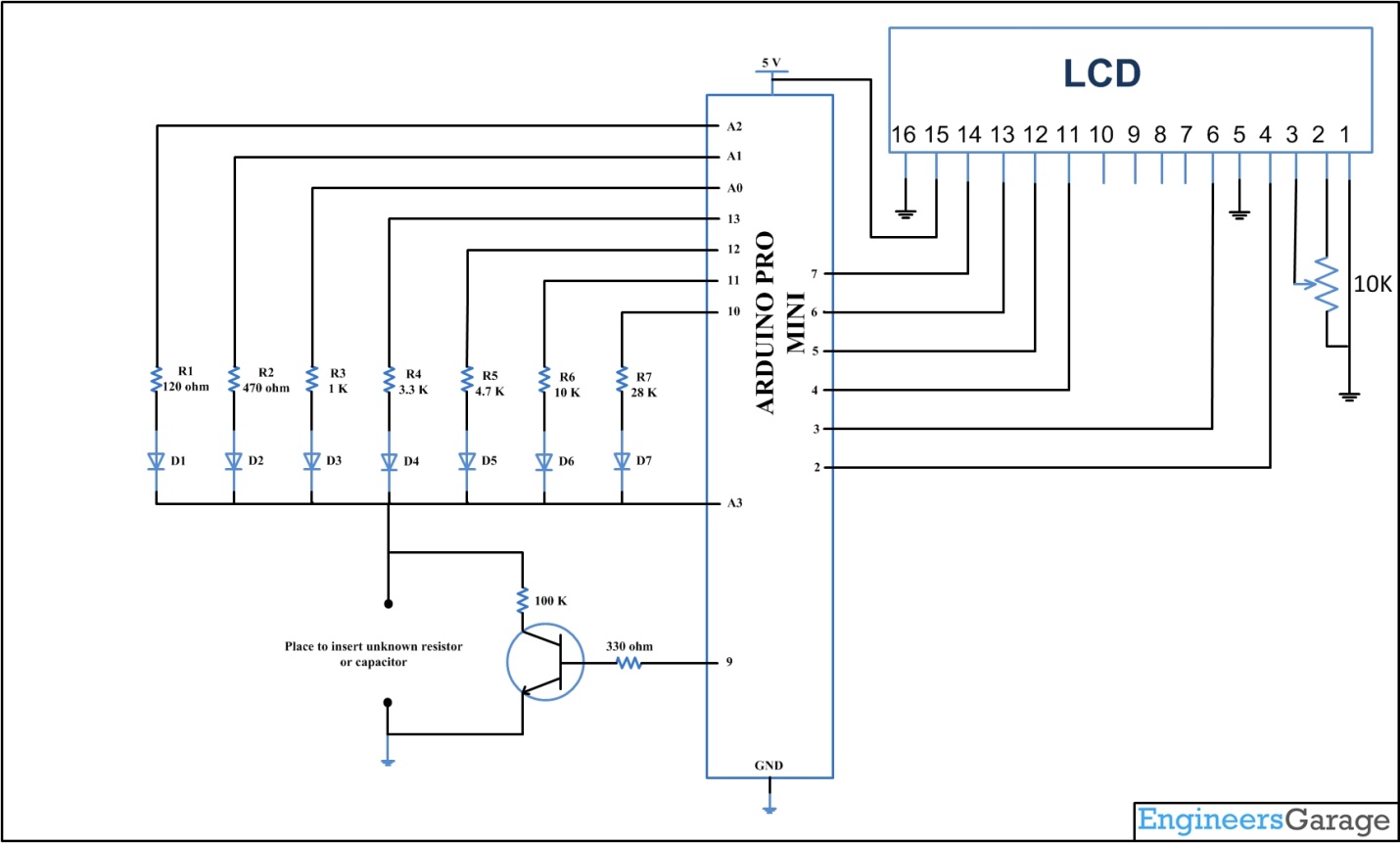
Auto ranging Resistance Sensor Unit:
A basic voltage divider circuit is used as the Resistance Sensing Unit to provide an output, which is the voltage equivalent of the unknown resistor as the input. From this output voltage we can calculate the value of unknown resistance, detect the diode type or detect a continuous path. For more details you can refer here.
A scheme for estimating the value of unknown resistance value roughly and then putting a matching resistor in place of R2 is what we need here and this method is called auto ranging. The circuit given below demonstrates auto ranging. For more details you can refer here.
RC Charging circuit:
The Capacitance sensor in this project is an RC discharging circuit in which the unknown capacitor is discharged through a known resistor. An RC discharging circuit is a circuit in which a capacitor and a resistor are connected in parallel. In an RC discharging circuit the time taken for the capacitor to discharge through the resistor to half the voltage before starts discharging is dependent on the values of resistance and capacitance. For more details refer this link.
Isolating circuit:
Digital pin 9 is used to isolate resistance and capacitance sensing circuit by means of proving base signal to the npn transistor, which is used to isolate 100k resistor while measuring resistance and adding 100k while measuring capacitance. This circuit isolates 100k resistor which is used to create RC circuit from the auto ranging voltage divider circuit to avoid mixing up of these sensing circuits.
Processor unit:
The processor unit in this project is the Arduino board and it uses the ADC module to read the output voltage from the Sensor Unit. On the Arduino board, we are using an 8 channel, 10 bit ADC with the reference voltage pin connected to 5 V. The ADC reads the voltage V2 and generates an equivalent value ‘ValueADC‘at the ADC register. For more details refer this link.
Display Unit:
The display unit in this project uses a common 16*2 LCD on which the Arduino displays the resistor value and diode type. The LCD has been wired in four bit mode to reduce the number of output pins of the Arduino board to be used. The code running on the Arduino used the library function analogRead () to obtain the ADC value and Lcd.print () to display the data on 16*2 LCD.

Fig. 2: Prototype of Arduino Based Resistance Capacitance Meter designed on Breadboard
Circuit Diagrams
Project Video
Filed Under: Electronic Projects
Filed Under: Electronic Projects

Questions related to this article?
👉Ask and discuss on EDAboard.com and Electro-Tech-Online.com forums.
Tell Us What You Think!!
You must be logged in to post a comment.