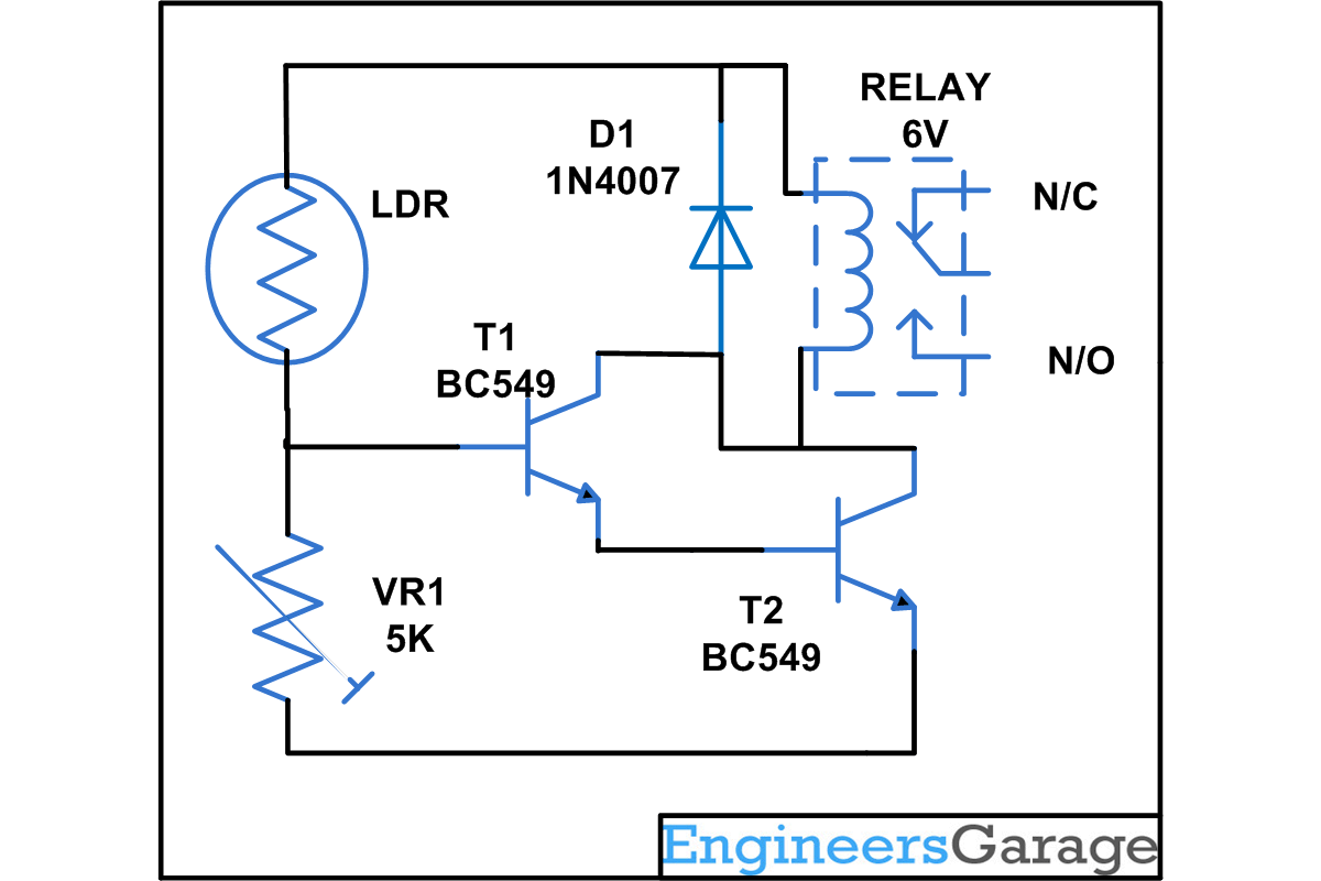
Two transistors with a common collector configuration and connected in a cascaded form constitute a Darlington Pair. While Darlington pairs can be made on a breadboard using a few electronic components, there are IC available that work as them and thus aid in making a circuit simple and easy to be operated.
A darlington pair has various applications associated with it and one of them is to use it as a switch. As the transistor's collector current is proportionally limited by its base current, it can be used as a current-controlled switch. This simple project can be used in various application like alarm circuits, in electronics control circuit to on and off the device.
In this project, the first transistor’s emitter feeds into the second transistor’s base and as a result the input signal gets amplified by the time it reaches the output. When light falls on the LDR, its resistance reduces. The bias voltage is supplied to the transistor and this voltage is enough to make the transistor and relay work. A variable resistor is also connected on the base of transistor to adjust the sensitivity.
Circuit Diagrams
Project Components
Filed Under: Electronic Projects


Questions related to this article?
👉Ask and discuss on Electro-Tech-Online.com and EDAboard.com forums.
Tell Us What You Think!!
You must be logged in to post a comment.