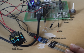
In Part I of this tutorial, we learned how to present data (or values) using a potentiometer (POT) and an organic light-emitting diode (OLED) display. For this project, the POT was an analog sensor (potentiometers can also be digital), which acts as a resistor to control the flow of an electric current. The OLED technology…
Solar Panel Parameters Monitoring Using Arduino
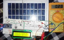
There are Power Stations for Maintaining or Monitoring the Power Circuits or Parameters related to Solar Panel. Parameters like Voltage, Temperature, Light Intensity and Current, which are important to monitor. The Monitoring of these parameters are also important in Households too. So, here we discuss about, How to Monitor Solar Panel Parameters.Working of this circuit is very common. In this circuit all the parameters are in the form of an Analog Form or nature. We have to only convert them in Digital Form or Nature and display these Digital values on the LCD. Some additional circuits are also required for proper Measurement.
Basic Electronics 10 – Dependent Resistors
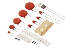
We have already discussed fixed resistors and variable resistors. Interestingly, resistors are not just limited to be used for limiting current, dropping voltage and dissipating power. There are many special types of resistors which work as transducers too and so, they can be used as sensors in the circuits. A transducer is a device which…
Simple LDR Dark Sensor Circuit
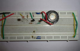
The circuit described here stops the musical sound when darkness is detected like when you put your hand above the sensor. This circuit can be used as morning alarm. Install it on your window so when the light falls on it will start giving you melodious sound to wake up. In night you can use it to switch off the light of staircase. When you switch off the light of your room with little modification like you can connect relay at output (in place of speaker) to off the bulb. This circuit can be operated with pencil cell as it require less only 3V for its operation. It can easily be mounted because of number of components used in circuit are quite small. LDR is a device whose sensitivity depends upon the intensity of light falling on it.
Automatic light/dark indicator using Opam and LDR
Automatic light/dark activated systems have very common utilities in day to day life. For example, street lighting at night, morning alarm, automatic emergency [[wysiwyg_imageupload::]]light, dark activated buzzers and so on. The project explained here can be used in several such systems. This circuit has a sensor component which works in response to the ambient light condition. The output of this sensor is compared with a set reference value and whenever the light condition changes from dark to light or light to dark, the output goes high. In this project, the surrounding illumination is observed by a light dependent resistor (LDR) which acts as a sensor for the circuit. The voltage drop across this LDR corresponds to a particular intensity of light. Read on more to find out how the circuit is made and how it works.
Light dependent frequency variation using LDR
This circuit responds to the change in light illumination in the form of varying frequency which can be observed through a flashing LED as output. The idea of [[wysiwyg_imageupload::]]this project is to use an LDR in place of a fixed value resistor which in turn generates a particular frequency. The generated frequency corresponds to the light conditions of the ambience.This concept finds popular application in motor speed control where the output is connected to motor driver circuit. Disco light is another interesting application of the idea where the lighting pattern keeps on changing. The circuit of this project uses NE555 to generate a continuous series of pulses in astable mode. The frequency of these pulses is obtained based on values of two resistors and a capacitor. Keep on reading to find out more information on the circuit and its working.
Working of light dependent resistor using transistor
This circuit based project explains the principle of operation of LDR (light dependence resistor). The circuit has various applications like shadow alarm, automatic [[wysiwyg_imageupload::]]night/morning lamp. As the name suggests, LDR is a type of resistor whose working depends upon only on the light falling on it. The resistor behaves as per amount of light and its output directly varies with it. In general, LDR resistance is minimum (ideally zero) when it receives maximum amount of light and goes to maximum (ideally infinite) when there is no light falling on it. A critical factor that decides LDR’s working is the frequency of light which should cross a threshold value so as to make LDR respond. Keep on reading to find out how the circuit is designed and how it is made to work.
Green House Monitoring Using Arduino
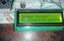
In today’s greenhouses, many parameter measurements are required to monitor and control for the good quality and productivity of plants. But to get the desired results there are some very important factors which come into play like Temperature, Humidity, Light and Water, which are necessary for a better plant growth. Keeping these parameters in mind I have built an Automatic Green House Controlling and Monitoring System over GSM module using Arduino. This system is very efficient for growing good quality plants. The other important part of this project is that it is fully automatic. Arduino automatically turns on and turn offs the appliances.
DIY: LASER Based Pulse Transmitter and Receiver
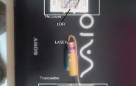
The circuit presented here transmits pulses wirelessly to long distance (more than 20 meter) using keychain LASER (readily available in market). A transmitter generates continuous pulses that are fed to LASER. LASER blinks at the rate of pulse frequency and emits light pulses. LDR on the receiver side, detects this light pulses and reproduces it at the output. So the same pulses that are generated at transmitter side can be received at receiver side to longer distance.To begin with the first thing that is required for this project is to prepare LASER. So let us start with how to prepare a LASER. LASER key-chains available in the market are like this. To prepare it for the project we need to take out its anode and cathode terminals to provide pulses. In order to remove button cells and keychain part from backside of the keychain. You will see one small spring, which is cathode terminal. Connect one wire with this as shown in the figure below.
DIY : Short Range Optical Pulse Transmitter and Receiver
This project demonstrates how pulses can be transmitted from one place to another place wirelessly using light as medium. One LED is connected at the transmitter side that blinks at frequency of applied pulses. At the receiver side, Light Dependent Resistor (LDR) is used to receive light pulses. IC555 is used at both ends. At transmitter side it is used to generate continuous pulses with variable frequency output from 1 Hz to 10 Hz. At receiver side it is used to generate same pulses as per the trigger input applied by LDR. Note – for visual effect (demonstration) the pulse frequency is kept low. The frequency can be kept high in terms of KHz also.
Wireless monitoring and controlling rescue robot using Zigbee
The robot is operated through PC using wireless technology using zigbee and using wireless camera we can view both audio and video on the TV. This robot has a high power LED which acts as a light source when light intensity inside the pipe is low .It is a low cost robot used to monitor the changes of different parameters in the industrial pipes. By connecting temperature sensor to the robot we can get the temperature of dangerous zones in PC itself. By connecting smoke sensor to the robot we can get the information related concentration of smoke or gases in respective fields.
Light Tracker Demonstration
Electricity is the most required and important element of human life. We cannot imagine our day to day life without electricity. Electricity is generated using conventional (coal, diesel) and non conventional (water, wind, sunlight) energy sources. The recent and latest trend is to generate electricity from solar energy. The solar panel (made up of solar-photovoltaic cells) converts solar energy in to electrical
Line Following Robot
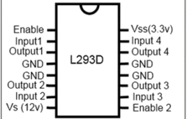
This circuit describe a simple line following robot which a you can easily make in your homes because it does not contains any complex digital circuitry and this can be made without using any microcontroller. In this circuit the robot the will follow a white line on black surface. This simple circuit is made with the help of single IC that is L293D and few more commonly known components like LDR and LED. LDR which is working as a sensor here. LDR is basically made up of semiconductor material. Semiconductor material has energy band where electrons and holes exist.
LDR Based Automatic Lamp
This circuit is based on Light Dependent Resistor (LDR) which will turn on LED’s whenever darkness is sensed in room. You can put this small lamp in your child’s room as a simple emergency lamp to avoid panic situation in case of sudden power failure. As it provide ample of light in the room so that your child can easily come out of room. Important feature of this circuit is it automatically become on by sensing the darkness so no need to search for switch.And it is powered by a rechargeable battery which charges automatically by the AC power supply so no need to worry about the battery backup. You can use adapter readily available in market or make your own. And when light comes it automatically off the lamp so need to off the lamp manually.
CD 4060 Based Security Alarm
In current times, it is necessary to have some security at home. To avoid acts of vandalism and thefts, we need instant responsive security alarms that are active [[wysiwyg_imageupload::]]all the time. This circuit is very helpful at this situation. We have a smart security alarm which can be used in home, in your locker or in cash box guard that thwarts the theft attempt by activating an emergency alarm.The circuit is built around the CD4060 and few more components. IC CD4060 is 14 stage ripple carry binary counter, divider and an oscillator. Its built in oscillator is main feature of this IC that’s why it can be used in numerous application like flasher, clock generator in timer circuits.Read more to find out working of the circuit with the help of circuit diagram, description and detailed information about the components used.
LED Lamp Using CA3140 IC
Shown here is a low power consuming LED lamp circuit which starts to grow after light intensity goes below a threshold level of detection. This is not a switch [[wysiwyg_imageupload::]]based circuit, thus needs no human interference in order to turn it ON or OFF. Circuit is based on IC CA3140 which is a operational amplifier which combine the voltage of PMOS transistor with high voltage bipolar transistor on single chip, Light depending resistor(LDR) whose resistance dependent upon the amount of light falling on it and few more components. The circuit uses an operational amplifier CA3140 whose pins 2 and 3 act as inverting and non inverting inputs. Keep on reading to find out how the circuit is constructed and how it works.
Motion Controller using Stepper Motor
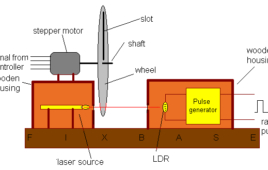
This system is the example of close loop control system for maintains the speed of stepper motor constant. The speed of stepper motor is sensed and feedback to controller. Controller will compare it with set value and if there is deviation then it will either increase or decrease the speed.In most of the industries the constant speed of motor is required and that should not be fall / exceed beyond specified limit. to get the precise RPM and control stepper motor is the best.The stepper motor is placed on top of laser as shown. The slotted wheel is coupled with the shaft of motor. The wheel is such a big that it can interrupt the laser beam falling on LDR. Now as the motor rotates the slotted wheel also rotates. The beam will fall on LDR only when the slot comes. This will produce one pulse. So every time when slot come in line with LDR and laser, one pulse is produced. Thus the rotation of motor is converted in to pulse that can be counted.
CD 4060IC based Message Display Circuit
This simple message display can be used to display any message such as warnings, wishes, address notifications etc. as it will automatically turn ON at night or in [[wysiwyg_imageupload::]]dark. This circuit is based on CD4060 IC, LDR and few more components so that we can be easily made and can be gifted to friends. Here total of 12 bright LED glow inside the four segments (I through IV as shown in fig below) of the message plate to display different message. We can use bright white LED’s or different color LED’s to indicate different words. In this circuit, different segments glow for different duration of time. IC CD4060 is 14 stage ripple carry binary counter, divider and an oscillator. Its built in oscillator is main feature of this IC, so it can be used in numerous applications like flasher, clock generator in timer circuits. The resistance of LDR is very high in darkness, which reduces to minimum when LDR is in light.
Electronic alarm for cash box, lockers
The project presented can be used as a smart circuit for the cash box that thwarts any theft attempt by activating an emergency alarm. This can also be used to [[wysiwyg_imageupload::]]trigger any external burglar alarm by connecting a relay to the output of the circuit. The circuit is built around a NAND gate IC in which all gates are used as an inverter. The circuit is based on the concept of Light Dependant Register (LDR) whose resistance varies with the intensity of light falling on it. This small circuit can also be installed in a locker system where if somebody tries to open the locker, the light will fall on the LDR and the circuit will start sounding with the help of buzzer connected to the relay. A switch is also provided so that the circuit can be switched off when not in use to save the battery power.
Relay operation using Darlington Pair
Two transistors with a common collector configuration and connected in a cascaded form constitute a Darlington Pair. While Darlington pairs can be made on a [[wysiwyg_imageupload::]]breadboard using a few electronic components, there are IC available that work as them and thus aid in making a circuit simple and easy to be operated.A darlington pair has various applications associated with it and one of them is to use it as a switch. As the transistor’s collector current is proportionally limited by its base current, it can be used as a current-controlled switch. This simple project can be used in various application like alarm circuits, in electronics control circuit to on and off the device.

