Aim: to design the gsm sim card reader and to interface it to the pc.
Components required:
· Ic 74hc04(inverter). (2 ic’s means 8 gates)
· Crystal oscillator. (just one of about 3.5Mhz)
· 10k ohm resistor. (10 in number)
· Transistor –bc293c. (3 in number)
· Diode. (3 in number)
· 1M ohm resistor
· Led diode
· Capictor each of 470uf(2 in number),100nf(2 in number),33pf(3‘s).
· Rs 232 male or female whichever suitable for the connection.
· Simcard reader port of six pins.
Theory:
The sim card interfaces consists of the series of the impedance matching circuits as we see there are six pins and there are eight pins some of the sim’s. The termination resistor has a value of 1- 10k ohm for data line & reset line and here we have 1-2k ohm for the clk line.we here build the circuits as per the pin requirements as we see i have connected the crystal oscillator for the clk pin and the requirement is calculated Vsim pin is connected to the DTR of rs232 terminal, then the clk is to the crystal oscillator,these data lines simdata and Vsim terminalthe the RTS of rs232 is connected to the simrst pin ,the circuit shows almost all the pins covered this is done without using any other ic. We can get this in market rarely but as we know the chip is all integrated to the single cable usb line which has max 232 which converts the TTL logic to the computer logic.
Circuit diagram:
The sim connector and the pin specifications of the sim.
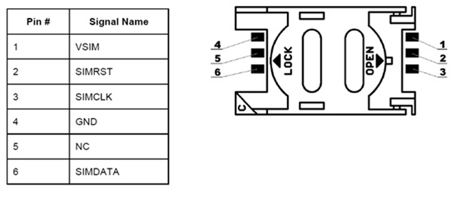
Fig. 1: Pin Diagram of Mobile SIM
Explanation:
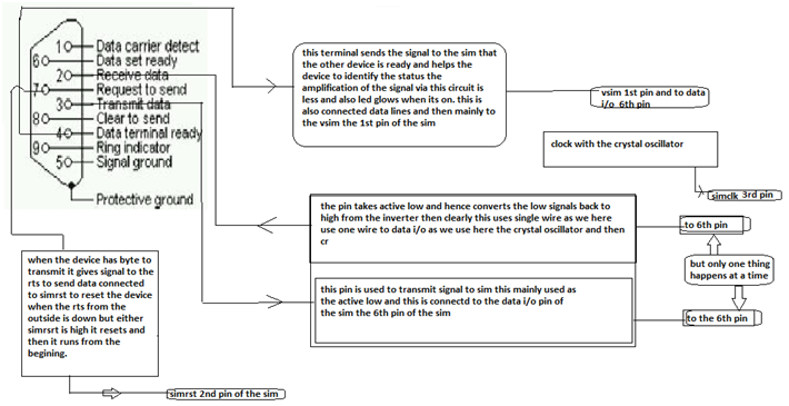
Fig. 2: Pin Diagram of RS-232 Serial Port
Clock circuit :this circuit helps the device to put the data in and out the sim card memory as we have same i/o pin is connected to the tx and rx via the transistor.
DTR terminal: this terminal is used mainly to make the sim ready to the transmit and receive operations and clearly this helps to transmit the data and helps to convey it to the memory of the sim and clearly we get the data done in putting into the sim memory .
RTS:this terminal is used to give the signal to simrst pin of the sim and makes it reset and this is done in the active low state and which also helps the program to start from the beginning for the new process.
Data i/o is only one and this is brought together by the single transistor and there is a possibility more advanced circuit in the place of that and also we can use more than one transistor or any other network analysis.
Installing the software:
The software installing should have a proper sim card accessible driver this helps in the connecting the device to the host i.e your pc.
But first we have to connect the RS232 to the usb and for this i have shown you the writing attached with this article and also we need to search the software properly.
For example we have the software like Simmaster2.0 which is very rarely got in the web also we have Simprobackup,by these softwares we can have backup also we can use it more if the we are smart enough.
Install the proper softare and also see we have the sim connected and we can extract all kinds of the codes of the particular sim in order to do know.
To run the software on your computer system, you require the following minimum hardware and software configuration settings:
Memory Required:
Hard Disk Space: 5 MB of Free Hard Disk Space
RAM Recommended: 128 MB RAM
Processor Required
Pentium class or equivalent processor
Operating System Required
Any of the Microsoft Windows OS including:
Windows XP
Windows 7
Results:
We can read the data in the sim card of six pin and clearly we can find more usefull codes in it by using suitable software.
Then we need to connect to the rs232 female pin and then convert the signal to the pin of the usb.
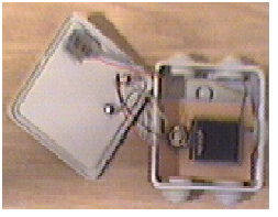
Fig. 3: Prototype of SIM Card Reader
Conversion of RS232 to usb port serial
Need for conversion:
RS-232 works on the voltage different than that of the TTL logic. As we see in RS-232 it represents 1 as-3 to -23 and ‘0’ from the +3 to +23. The need is for the circuits of microcontrollers, chips , ic’s ,etc can be interfaced from this conversion. Then from the other end we can use this to connect to the laptop or pc. Then from this we can modify various memory ,rom, codes etc by using a suitable software in the laptop or pc.

Fig. 4: Circuit Diagram of MAX232 based RS-232 to TTL Logic Converter
Pin Configuration and Simulation
PIN CONFIGURATION OF RS-232 DB-9:
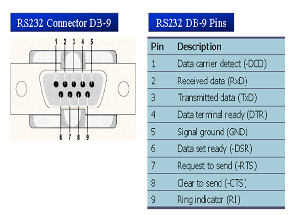
Fig. 5: Pin Diagram of RS-232 Connector
As we see that the data communication can be classified as DTE(data terminal equipment) and DCE(data connection equipment). The simple connection requires a atleast 3 pins that is for the transmission, receiving and ground. As we see i used only 3 pins from the RS-232 port which is used to connect for the MAX 232 ic. The remaining pins are to be connected for the circuit of the required chip or the circuit components of the chip.
DCD (Data Carrier Detect)
· The modem asserts signal DCD to inform the DTE that a vailed carrier has been detected and theat contact between it and the other modem is established.
RI (Ring Indicator)
· An output from the modem and an inpur to a PC indicates taht the telephone is ringing.
· It goes on and off in synchronous with the ringing sound.
Data Terminal Ready
When terminal is turned on, it sends out signal DTR to indicate that it is ready for communication.
Data Set Ready
When DCE is turned ON and has gone through self assert test, it assert DSR to indicate that it is ON for communication.
RTS (Request to Send): When the DTE device has byte to transmit, it asserts RTS to signal to modem that it has a byte of data to transmit.
CTS (Clear to Send)
When the modem has room for storing the data it is to receive, it sends out signal CTS to DTE to indicate that it can receive the data now.
Usb pin configuration:
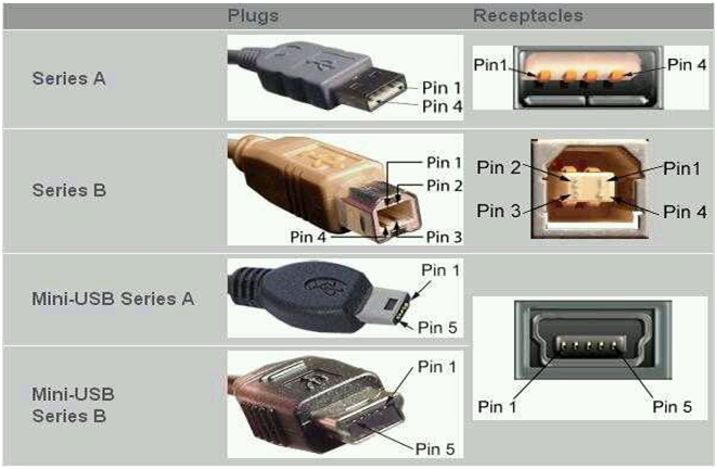
Fig. 6: Pin Diagrams of different types of USB Connectors
|
Pin
|
Color of wire
|
Type
|
Job
|
|
1
|
red
|
vcc
|
+5 volt
|
|
2
|
white
|
D-
|
Data-
|
|
3
|
green
|
D+
|
Data+
|
|
4
|
black
|
gnd
|
ground
|
|
|
|
|
|
Universal serial bus is a specification used for the connection between the devices and the pc’s.nowadays usb’s are replaced from various interfaces .usb can be used for the connection of the computer peripheral gps, mice keyboard etc.
Then we have pin config of usb as shown above. Now there are 7 types of the usb connectors. Half duplex differential signalling helps to combat the electromagnetic noise . the D- and D+ opertate together ,they are not separate simplex.usb 2.0 uses the 1.5Mbps signalling rate, but for the full bandwidth the signalling rate is12Mbps.
Note: connect this very specific and neatly.
Result: as we see the connections are to be specific and clear.
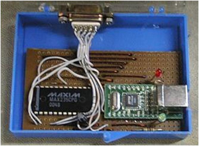
Fig. 7: Prototype of SIM Card Reader
(“do not use this for the illegal purposes we can read the card without barrier unlike in cable connection of the phone to a pc where we can’t hit the sim ,we are not responsible for the activities done by using this reader. THIS IS ONLY FOR THE EDUCATIONAL PURPOSE”)
Example of the software: sim pro
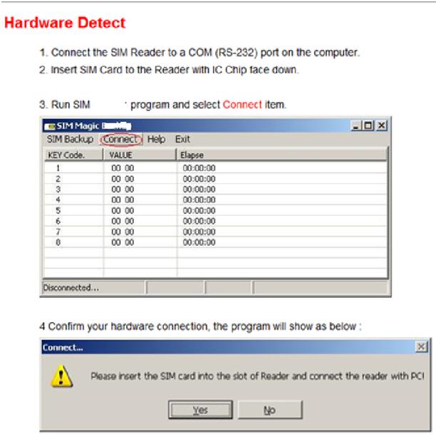
Fig. 8: Screenshot of instructions for detecting SIM Card
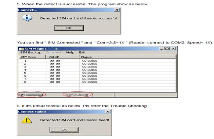
Fig. 9: Screenshot of Messages for successful and failed detection of SIM card
Filed Under: Electronic Projects


Questions related to this article?
👉Ask and discuss on EDAboard.com and Electro-Tech-Online.com forums.
Tell Us What You Think!!
You must be logged in to post a comment.