Engineers Garage

  • Electronic Projects & Tutorials
    • Electronic Projects
      • Arduino Projects
      • AVR
      • Raspberry pi
      • ESP8266
      • BeagleBone
      • 8051 Microcontroller
      • ARM
      • PIC Microcontroller
      • STM32
    • Tutorials
      • Sensor Series
      • 3D Printing
      • AI
      • ARDUINO Compatible Coding
      • Audio Electronics
      • Battery Management
      • Beginners Electronics Series
      • Brainwave
      • Digital electronics (DE)
      • Electric Vehicles
      • EMI/EMC/RFI
      • EVs
      • Hardware Filters
      • IoT tutorials
      • LoRa/LoRaWAN
      • Power Tutorials
      • Protocol
      • Python
      • RPI Python Programming
      • Sensors
      • USB
      • Thermal management
      • Verilog
      • VHDL
    • Circuit Design
    • Project Videos
    • Components
  • Articles
    • Tech Articles
    • Insight
    • Invention Stories
    • How to
    • What Is
  • News
    • Electronic Product News
    • Business News
    • Company/Start-up News
    • DIY Reviews
    • Guest Post
  • Forums
    • EDABoard.com
    • Electro-Tech-Online
    • EG Forum Archive
  • DigiKey Store
    • Cables, Wires
    • Connectors, Interconnect
    • Discrete
    • Electromechanical
    • Embedded Computers
    • Enclosures, Hardware, Office
    • Integrated Circuits (ICs)
    • Isolators
    • LED/Optoelectronics
    • Passive
    • Power, Circuit Protection
    • Programmers
    • RF, Wireless
    • Semiconductors
    • Sensors, Transducers
    • Test Products
    • Tools
  • Learn
    • eBooks/Tech Tips
    • Design Guides
    • Learning Center
    • Tech Toolboxes
    • Webinars & Digital Events
  • Resources
    • Digital Issues
    • EE Training Days
    • LEAP Awards
    • Podcasts
    • Webinars / Digital Events
    • White Papers
    • Engineering Diversity & Inclusion
  • Guest Post Guidelines
  • Advertise
  • Subscribe

SPEEDOMETER USING ARDUINO AND CAN PROTOCOL

By Prabakaran P.M January 16, 2024

Summary:

This Article is to make readers to explore about how Speedometer works in modern cars. Here you can get an idea on the CAN Bus which is used in the Communication of Sensors, Actuators and controllers in a car.

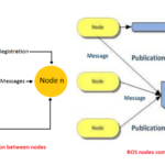
Controller Area Network or CAN protocol is a methodology of communication between various electronic devices like engine management systems, gear control, active suspension, ABS, airbags, lighting control, air conditioning, central locking etc. embedded in an automobile. For further learnings refer this article.

Prototype of Arduino Based Speedometer using CAN Interface

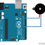
Fig. 1: Prototype of Arduino Based Speedometer using CAN Interface

Description:

Prerequisites & Equipment:

You are going to need the following:

  1. Two Arduino Board or Arduino clone(Here is a guide if you need)

  2. A 5v TTL -UART Bluetooth module.

  3. LCD, Proximity Sensor, DC Motor and Servo Motor.

  4. Arduino IDE for the programming.

  5. Two CAN Tranciever.

Here to simulate the engine RPM measurement, we are using Industrial proximity sensor used to measure the speed of rotating objects and a DC motor which is speed controlled by the Preset.

Inductive Proximity sensor:

For non-contact detection of metallic targets at ranges less than 50mm (2 inches) Inductive Proximity sensors are mostly used. These sensors have sensing area where an alternating electro-magnetic field is emitted, when a metal target enters the sensing area, eddy currents are induced in the target, which results in a change of state at the sensor output.

Here the output of the sensor will be high when a metal is placed near the sensing area and vice versa. Using this we can make an arrangement that gives only one high pulse for each rotation of the motor. Counting pulses for one minute can give the Rotations per Minute.

Speed Measurement:

This project uses an Inductive Proximity sensor to detect the presence of a metal. Whenever a metal comes near the sensor, it can detect it. Hence, this sort of sensor can be used to do a lot of things. For example, if we need to detect when a door is close, then we can attach a metal to the door and the sensor to the frame of the door. Whenever the door closes, the metal gets placed near the sensor and therefore we are able to detect that the door is closed.

This same principle can be used to make a speedometer for a bike or any other vehicle in a non-contact way by attaching a metal to the wheel and a sensor is placed somewhere in the frame of the bike, the time taken for one revolution can be measured by counting the time interval between the two detections.

The setup is made as follows, a screw is connected to the rotating part of the motor and it is projected to small distance. The motor is powered by 12V power supply.

The signal goes high when the screw is near to the sensor placed near the motor.

The numbers…

RPM = 60000000/timerrevCalc;

Where:

60 = seconds in a minute.

Duration = amount of time sensing area exposed to metal in uS.

1.4574 = the metal notch is 1.4574 times smaller than the remainder of the wheel, this number needs to be calculated and adjusted per application.

60000000 is a conversion from uS to just plain seconds.

This appears to be VERY fast at reading RPM. The RPM is calculated with EACH pulse. So instead of using an interrupt and have to wait the interrupt interval to refresh the data, the data come in after each pulse is timed. Also, when using interrupts, you have limited resolution. Example, 1 pulse counted over 250ms so 4 pulses per second or 240 RPM and 2 pulses per 250ms so 8 pulses per second or 480 RPM!!! 1 pulse increase will lead to 240RPM increase. To get better resolution, you need a longer interrupt interval. But , At the same time longer interrupt interval will lead to slower response.

Image showing CAN Bus connections with Arduino based Speedometer

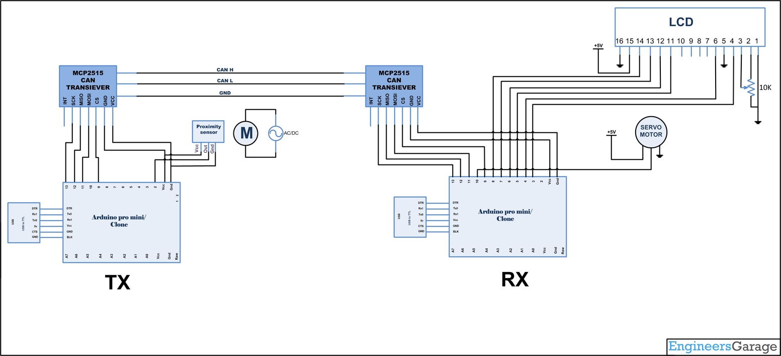
Fig. 2: Image showing CAN Bus connections with Arduino based Speedometer

Connections for the Arduino and Sensor in TX Side:

The sensor used here has three wires where, Red and black is VCC and GND and Green wire is the Digital output of the sensor. As stated previously output will go high when metal is near the sensing area.

The VCC of the sensor is connected to 5V. The GND of the sensor is connected to the GND pin of the Arduino. And the Vout or Digital output of the sensor is connected to Arduino’s interrupt pin (pin 2).

Running the program:

Load the program TX.ino after you save it onto your computer and open it in Arduino IDE .

  • Compile the program in the Arduino IDE

The following function is used to send the values to the CAN bus. Detailed instruction can be found here.

CAN.sendMsgBuf(0x70,0, 2, stmp);

Receiving CAN data and displaying in an LCD in RX Side:

Load the program RX.ino after you save it onto your computer and open it in Arduino IDE .

  • Compile the program in the Arduino IDE

The following function is used to receive the values from the CAN bus and to display in an LCD. Detailed instruction can be found here.

CAN.readMsgBuf(&len, buf);

Loading software for Arduino:

If you are new to Arduino you can start with here. You have to start with the Arduino IDE (Integrated Development Environment) from Arduino . Download the code from below link and upload it to the Arduino board.

The operation of the system is as follows:

  • The DISPLAY processor that waits for the current RPM message send from the COLLECTOR processor over the CAN bus.

  • The COLLECTOR processor measure the RPM, formats it, and sends to the DISPLAY processor over the CAN bus.

  • The DISPLAY processor reads the message from the CAN bus and then displays it on the LCD which is repeated.​​​​

    Hardware assembly:

Image showing Sensor Assembly on DC Motor for sensing its rotational speed

Fig. 3: Image showing Sensor Assembly on DC Motor for sensing its rotational speed

Image Showing Wiring of Inductive Proximity Sensor

Fig. 4: Image showing Inductive Proximity Sensor attached near Motor Assembly

Image Showing Wiring of Inductive Proximity Sensor

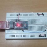
Fig. 5: Image showing wiring of Inductive Proximity Sensor

Typical Image of Inductive Proximity Sensor

Fig. 6: Typical image of Inductive Proximity Sensor

Make the circuit as is given by the circuit diagram. Make the circuit with your selected parts and connect the motors to the circuit.

You may also like:


  • How to play musical notes on Arduino

  • What are the top tools for developing embedded software?

  • What is the Modbus protocol and how does it work?

  • What is a Robot Operating System (ROS)?

  • What is FreeRTOS?
  • Getting Started With Arduino With Simple LED Blinking Code Circuit Setup On Breadboard
    Getting started with Arduino – (Part 1/49)

Circuit Diagrams

Circuit-Diagram-Arduino-Based-Speedometer-Using-CAN-Interface

Project Video


Filed Under: Electronic Projects


Next Article

← Previous Article
Next Article →

Questions related to this article?
👉Ask and discuss on EDAboard.com and Electro-Tech-Online.com forums.


Tell Us What You Think!! Cancel reply

You must be logged in to post a comment.

Submit a Guest Post

submit a guest post

EE TECH TOOLBOX

“ee
Tech Toolbox: Power Efficiency
Discover proven strategies for power conversion, wide bandgap devices, and motor control — balancing performance, cost, and sustainability across industrial, automotive, and IoT systems.

EE Learning Center

EE Learning Center
“engineers
EXPAND YOUR KNOWLEDGE AND STAY CONNECTED
Get the latest info on technologies, tools and strategies for EE professionals.

HAVE A QUESTION?

Have a technical question about an article or other engineering questions? Check out our engineering forums EDABoard.com and Electro-Tech-Online.com where you can get those questions asked and answered by your peers!


RSS EDABOARD.com Discussions.

  • How to achieve large ratio current mirror?
  • Biasing an AC signal
  • Power amplifier stability
  • MOSFET thermal noise in Weak vs Strong inversion
  • Generation and transformation of waveform

RSS Electro-Tech-Online.com Discussions

  • Need a fresh eye on my first PCB
  • restarting this Christmas project
  • desoldering
  • Unknown, to me, electric motor fitting
  • Can a small solar panel safely trickle-charge old NiMH AA batteries?

Featured Tutorials

Real Time Hardware Filter Design

  • Practical implementation of bandpass and band reject filters
    Practical implementation of bandpass and band reject filters
  • Practical application of hardware filters with real-life examples
    Practical application of hardware filters with real-life examples
  • A filter design example
    A filter design example
  • Types of filter responses
    Types of filter responses
  • What are the two types of hardware filters?
    What are the two types of hardware filters?
  • What are hardware filters and their types?
    What are hardware filters and their types?
More Tutorials >

Recent Articles

  • Taiwan Semiconductor adds 24-V automotive TVS devices
  • ST e-fuse controller enables fast, flexible automotive power protection
  • Posifa sensors improve low-flow accuracy in compact systems
  • Acopian releases low-profile power supplies rated to 900 W
  • Octavo Systems OSDZU-3 REF Development Platform

EE ENGINEERING TRAINING DAYS

engineering
Engineers Garage
  • Analog IC TIps
  • Connector Tips
  • Battery Power Tips
  • EDABoard Forums
  • EE World Online
  • Electro-Tech-Online Forums
  • EV Engineering
  • Microcontroller Tips
  • Power Electronic Tips
  • Sensor Tips
  • Test and Measurement Tips
  • 5G Technology World
  • Subscribe to our newsletter
  • About Us
  • Contact Us
  • Advertise

Copyright © 2025 WTWH Media LLC. All Rights Reserved. The material on this site may not be reproduced, distributed, transmitted, cached or otherwise used, except with the prior written permission of WTWH Media
Privacy Policy

Search Engineers Garage

  • Electronic Projects & Tutorials
    • Electronic Projects
      • Arduino Projects
      • AVR
      • Raspberry pi
      • ESP8266
      • BeagleBone
      • 8051 Microcontroller
      • ARM
      • PIC Microcontroller
      • STM32
    • Tutorials
      • Sensor Series
      • 3D Printing
      • AI
      • ARDUINO Compatible Coding
      • Audio Electronics
      • Battery Management
      • Beginners Electronics Series
      • Brainwave
      • Digital electronics (DE)
      • Electric Vehicles
      • EMI/EMC/RFI
      • EVs
      • Hardware Filters
      • IoT tutorials
      • LoRa/LoRaWAN
      • Power Tutorials
      • Protocol
      • Python
      • RPI Python Programming
      • Sensors
      • USB
      • Thermal management
      • Verilog
      • VHDL
    • Circuit Design
    • Project Videos
    • Components
  • Articles
    • Tech Articles
    • Insight
    • Invention Stories
    • How to
    • What Is
  • News
    • Electronic Product News
    • Business News
    • Company/Start-up News
    • DIY Reviews
    • Guest Post
  • Forums
    • EDABoard.com
    • Electro-Tech-Online
    • EG Forum Archive
  • DigiKey Store
    • Cables, Wires
    • Connectors, Interconnect
    • Discrete
    • Electromechanical
    • Embedded Computers
    • Enclosures, Hardware, Office
    • Integrated Circuits (ICs)
    • Isolators
    • LED/Optoelectronics
    • Passive
    • Power, Circuit Protection
    • Programmers
    • RF, Wireless
    • Semiconductors
    • Sensors, Transducers
    • Test Products
    • Tools
  • Learn
    • eBooks/Tech Tips
    • Design Guides
    • Learning Center
    • Tech Toolboxes
    • Webinars & Digital Events
  • Resources
    • Digital Issues
    • EE Training Days
    • LEAP Awards
    • Podcasts
    • Webinars / Digital Events
    • White Papers
    • Engineering Diversity & Inclusion
  • Guest Post Guidelines
  • Advertise
  • Subscribe