Engineers Garage

  • Electronic Projects & Tutorials
    • Electronic Projects
      • Arduino Projects
      • AVR
      • Raspberry pi
      • ESP8266
      • BeagleBone
      • 8051 Microcontroller
      • ARM
      • PIC Microcontroller
      • STM32
    • Tutorials
      • Audio Electronics
      • Battery Management
      • Brainwave
      • Electric Vehicles
      • EMI/EMC/RFI
      • Hardware Filters
      • IoT tutorials
      • Power Tutorials
      • Python
      • Sensors
      • USB
      • VHDL
    • Circuit Design
    • Project Videos
    • Components
  • Articles
    • Tech Articles
    • Insight
    • Invention Stories
    • How to
    • What Is
  • News
    • Electronic Product News
    • Business News
    • Company/Start-up News
    • DIY Reviews
    • Guest Post
  • Forums
    • EDABoard.com
    • Electro-Tech-Online
    • EG Forum Archive
  • DigiKey Store
    • Cables, Wires
    • Connectors, Interconnect
    • Discrete
    • Electromechanical
    • Embedded Computers
    • Enclosures, Hardware, Office
    • Integrated Circuits (ICs)
    • Isolators
    • LED/Optoelectronics
    • Passive
    • Power, Circuit Protection
    • Programmers
    • RF, Wireless
    • Semiconductors
    • Sensors, Transducers
    • Test Products
    • Tools
  • Learn
    • eBooks/Tech Tips
    • Design Guides
    • Learning Center
    • Tech Toolboxes
    • Webinars & Digital Events
  • Resources
    • Digital Issues
    • EE Training Days
    • LEAP Awards
    • Podcasts
    • Webinars / Digital Events
    • White Papers
    • Engineering Diversity & Inclusion
    • DesignFast
  • Guest Post Guidelines
  • Advertise
  • Subscribe

CAR REVERSE GUIDE USING CAN PROTOCOL

By Prabakaran P.M January 16, 2024

Summary:

This Project is to design and implement an Ultrasonic Vehicular Parking Aid Display, which notifies the driver about obstacles coming in the way of parking. In light of the emerging traffic situation where parking space is at a premium such a device can be very useful and also facilitate parallel parking easily. The implementation of the idea with the ultrasonic sensor interfaced with Arduino and the technical details of this project follows later.

Here you will get idea about the programming of the Arduino to interface with CAN Controller (MCP2515) to act as a transceiver. Here two Arduino are used, one is for sensing the distance using Ultrasonic sensor and another one is to display the values received through the CAN BUS.

Description:

Prerequisites & Equipment:

You will need the following:

  1. Two Arduino Board or Arduino clone (Here is a guide if you need)

  2. A 5v TTL -UART Bluetooth module.

  3. LCD and Ultrasonic Sensor (HC-SR04).

  4. Arduino IDE for the programming.

  5. Two CAN Transceiver.

Working Principle:

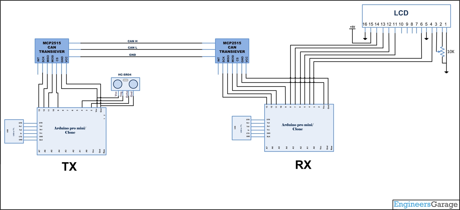
This Project includes two distinct parts, transmitter section and a receiver section. Receiver section consists of an Arduino and LCD to show the Distance of obstacle received from the CAN Bus. The Transmitter section consists of the Ultrasonic sensor interfaced with Arduino. The communication between both sections are carried out by the MCP2515 CAN transceiver.

Block Diagram Arduino based Car Reverse Guidance System

Fig. 1: Block Diagram Arduino based Car Reverse Guidance System

We are using HC-SR04 ultrasonic sensors on the transmitter side placed in the rear side of the vehicle, used to get the distance measurement. The HC-SR04 ultrasonic sensor uses sonar to determine distance to an object like bats do. It offers excellent non-contact range detection with high accuracy. The range of Measurement is 2cm to 400 cm or 1” to 13 feet. It operation is not affected by sunlight or black material. It comes in module with ultrasonic transmitter and receiver.

Features:

  1. Power Supply :+5V DC

  2. Quiescent Current : <2mA

  3. Working Current: 15mA

  4. Effectual Angle: <15°

  5. Ranging Distance : 2cm – 400 cm/1″ – 13ft

  6. Resolution : 0.3 cm

  7. Measuring Angle: 30 degree

  8. Trigger Input Pulse width: 10uS

  9. Dimension: 45mm x 20mm x 15mm

Wiring:

Pins:

  1. VCC: +5VDC

  2. Trig : Trigger (INPUT)

  3. Echo: Echo (OUTPUT)

  4. GND: GND

Connect the sensor to the Arduino as shown below

       HC-Sr04        Arduino

       Pin 1             Vcc

       Pin 2             GPIO 4

       Pin 3             GPIO 2

       Pin 4             Gnd

Running the program:

Load the program TX.ino after you save it onto your computer and open it in Arduino IDE .

  • Compile the program in the Arduino IDE

The following function is used to send the values to the CAN bus. Detailed instruction can be found here.

CAN.sendMsgBuf(0x70,0, 2, stmp);

Receiving CAN data and displaying in an LCD:

Load the program RX.ino after you save it onto your computer and open it in Arduino IDE .

  • Compile the program in the Arduino IDE

The following function is used to receive the values from the CAN bus and to display in an LCD. Detailed instruction can be found here.

CAN.readMsgBuf(&len, buf);

Loading software for Arduino:

If you are new to Arduino you can start with here. You have to start with the Arduino IDE (Integrated Development Environment) from Arduino . Download the code from below link and upload it to the Arduino board.

The operation of the system is as follows:

  • The DISPLAY processor that waits for the current distance message send from the COLLECTOR processor over the CAN bus.

  • The COLLECTOR processor measure the distance, formats it, and sends to the DISPLAY processor over the CAN bus.

  • The DISPLAY processor reads the message from the CAN bus and then displays it on the LCD which is repeated every second.

Hardware assembly:

Prototype of Arduino Robot demonstrating Car Reverse Guidance System

Fig. 2: Prototype of Arduino Robot demonstrating Car Reverse Guidance System

Image showing CAN Transmitter and Receiver mounted over Arduino Robot Car

Fig. 3: Image showing CAN Transmitter and Receiver mounted over Arduino Robot Car

Image showing CAN Receiver Module mounted on Arduino Robot Car

Fig. 4: Image showing CAN Receiver Module mounted on Arduino Robot Car

Image showing CAN Receiver Module mounted on Arduino Robot Car

Fig. 5: Image showing Ultrasonic Sensor and CAN Transmitter Module mounted on Arduino Robot Car

Make the circuit as is given by the circuit diagram. Make the circuit with your selected parts and connect the motors to the circuit.

You may also like:


  • What are different types of industrial robots?

  • How does LoRa modulation enable long-range communication?

  • What battery chemistries are used in electric vehicles?

  • What are the different types of EV charging connectors?

  • What types of motors are used in electric vehicles?

  • What is the role of embedded software in electric vehicles?

Circuit Diagrams

Circuit-Diagram-Car-Reverse-Guidance-Prototype-Used-Arduino-Robotic-Car

Project Video


Filed Under: Electronic Projects


Next Article

← Previous Article
Next Article →

Comments

  1. [email protected] says

    March 6, 2023 at 3:59 pm

    i want the transmitter and Receiver code please

    Log in to Reply

Questions related to this article?
👉Ask and discuss on EDAboard.com and Electro-Tech-Online.com forums.


Tell Us What You Think!! Cancel reply

You must be logged in to post a comment.

EE TECH TOOLBOX

“ee
Tech Toolbox: 5G Technology
This Tech Toolbox covers the basics of 5G technology plus a story about how engineers designed and built a prototype DSL router mostly from old cellphone parts. Download this first 5G/wired/wireless communications Tech Toolbox to learn more!

EE Learning Center

EE Learning Center
“engineers
EXPAND YOUR KNOWLEDGE AND STAY CONNECTED
Get the latest info on technologies, tools and strategies for EE professionals.

HAVE A QUESTION?

Have a technical question about an article or other engineering questions? Check out our engineering forums EDABoard.com and Electro-Tech-Online.com where you can get those questions asked and answered by your peers!


RSS EDABOARD.com Discussions

  • Exporting sensor readings as data...
  • Inconsistent Charge Termination Voltage with battery charger
  • 21V keeps getting shorted to my UART line.
  • Voltage mode pushpull is a nonsense SMPS?
  • Voltage mode push pull with extra DC blocking capacitor

RSS Electro-Tech-Online.com Discussions

  • Is AI making embedded software developers more productive?
  • Why can't I breadboard this oscillator?
  • using a RTC in SF basic
  • Parts required for a personal project
  • Cataract Lens Options?

Featured – RPi Python Programming (27 Part)

  • RPi Python Programming 21: The SIM900A AT commands
  • RPi Python Programming 22: Calls & SMS using a SIM900A GSM-GPRS modem
  • RPi Python Programming 23: Interfacing a NEO-6MV2 GPS module with Raspberry Pi
  • RPi Python Programming 24: I2C explained
  • RPi Python Programming 25 – Synchronous serial communication in Raspberry Pi using I2C protocol
  • RPi Python Programming 26 – Interfacing ADXL345 accelerometer sensor with Raspberry Pi

Recent Articles

  • GigaDevice launches GD32C231 MCU series with 48MHz Cortex-M23 core and 64KB Flash
  • Advanced Energy releases 425 W CF-rated medical power supply in 3.5 x 6 x 1.5-inch format”
  • LEM combines shunt and Hall effect sensing in 2000 A current measurement unit
  • What is AWS IoT Core and when should you use it?
  • AC-DC power supply extends voltage range to 800 V DC

EE ENGINEERING TRAINING DAYS

engineering

Submit a Guest Post

submit a guest post
Engineers Garage
  • Analog IC TIps
  • Connector Tips
  • Battery Power Tips
  • DesignFast
  • EDABoard Forums
  • EE World Online
  • Electro-Tech-Online Forums
  • EV Engineering
  • Microcontroller Tips
  • Power Electronic Tips
  • Sensor Tips
  • Test and Measurement Tips
  • 5G Technology World
  • Subscribe to our newsletter
  • About Us
  • Contact Us
  • Advertise

Copyright © 2025 WTWH Media LLC. All Rights Reserved. The material on this site may not be reproduced, distributed, transmitted, cached or otherwise used, except with the prior written permission of WTWH Media
Privacy Policy

Search Engineers Garage

  • Electronic Projects & Tutorials
    • Electronic Projects
      • Arduino Projects
      • AVR
      • Raspberry pi
      • ESP8266
      • BeagleBone
      • 8051 Microcontroller
      • ARM
      • PIC Microcontroller
      • STM32
    • Tutorials
      • Audio Electronics
      • Battery Management
      • Brainwave
      • Electric Vehicles
      • EMI/EMC/RFI
      • Hardware Filters
      • IoT tutorials
      • Power Tutorials
      • Python
      • Sensors
      • USB
      • VHDL
    • Circuit Design
    • Project Videos
    • Components
  • Articles
    • Tech Articles
    • Insight
    • Invention Stories
    • How to
    • What Is
  • News
    • Electronic Product News
    • Business News
    • Company/Start-up News
    • DIY Reviews
    • Guest Post
  • Forums
    • EDABoard.com
    • Electro-Tech-Online
    • EG Forum Archive
  • DigiKey Store
    • Cables, Wires
    • Connectors, Interconnect
    • Discrete
    • Electromechanical
    • Embedded Computers
    • Enclosures, Hardware, Office
    • Integrated Circuits (ICs)
    • Isolators
    • LED/Optoelectronics
    • Passive
    • Power, Circuit Protection
    • Programmers
    • RF, Wireless
    • Semiconductors
    • Sensors, Transducers
    • Test Products
    • Tools
  • Learn
    • eBooks/Tech Tips
    • Design Guides
    • Learning Center
    • Tech Toolboxes
    • Webinars & Digital Events
  • Resources
    • Digital Issues
    • EE Training Days
    • LEAP Awards
    • Podcasts
    • Webinars / Digital Events
    • White Papers
    • Engineering Diversity & Inclusion
    • DesignFast
  • Guest Post Guidelines
  • Advertise
  • Subscribe