Here is the application that drives unipolar stepper motor as one enters desire no of rotations and desire RPM. This circuit rotates any unipolar stepper motor for no. Of rotations at set RPM both entered by user. Any stepper motor has basically three parameters that we can change direction, no of rotations and RPM. All these three parameter we can set here and then press start button to rotate motor. So this is actually a panel board for stepper motor where user can set the parameters through keypad and start the operation.
Let us start with panel design. The figure given below shows unipolar stepper motor control panel.

There are
· 20X2 LCD panel to display various messages and parameters.
· SPDT sliding switch is used to select direction of rotation
· 4X3 numeric keypad to enter parameters and start operation
· LED indicators to indicate rotating direction
· Stepper motor connector to connect unipolar stepper motor. (C – common, L1 – coil 1, L2 – coil 2 and likewise)
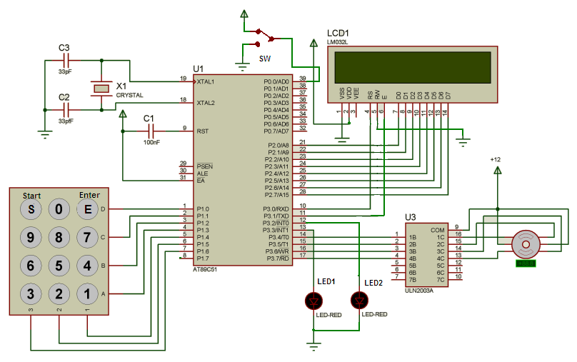
Now let us see the internal circuit diagram
As shown in Stepper Motor Driver Circuit Diagram (Circuit Diagram Tab), the one and only major component is micro controller 89C51 that will take care of all the operations. Other components are 20X2 LCD, current driver chip ULN2003A and 4×3 numeric keypad.
Connections: – all 4 rows of keypad are connected with P1.0-P1.3 and columns are connected with P1.4 – P1.6. Datalines (D0-D7) are connected with P2 and control lines Rs & En are connected with P3.0 & P3.1 respectively. Rw is directly grounded. 2 LEDs are connected with P3.2 and P3.3. P3.4 to P3.7 drives stepper motor through ULN chip. One SPDT switch connected to P0.0 to connect it with Vcc or Gnd. C1 is used for power on reset feature. Crystal X1 (12 MHz) along with 2 33pf capacitors provides clocking signal to 89C51.
Operation: –
o Initially the message “enter rotation in 2 digits” is displayed
o After pressing 2 digits as one enters it, again message “enter RPS in 2 digits” is displayed
o When both rotations and RPS are entered then message “press start” is displayed and system waits for start switch to be pressed
o Before pressing start switch one can select CW or CCW direction using SPDT switch.
o As one presses start switch the motor will start rotating. It rotates at entered RPS and completes desired no of rotations.
o If motor rotates CW then LED1 blinks at PRF (pulse repetition frequency) and if it rotates CCW then LED2 blinks.
o Again same above cycle repeats for next operation.
Now this entire operation is handled by the software program written in C language that is loaded in micro-controller 89C51. So now let us understand it.
Software program
Software program: –
write cmd function sends command byte to LCD. It takes one argument byte and sends it to P0
write data function sends data byte to be displayed on LCD. It also takes one argument byte and sends it to P0
write str function writes whole string (message) on LCD. It takes pointer as an argument that points address of first character of string. Then through pointer it sends all the character one by one to P0
LCD busy function provides delay after sending command or data byte to LCD
Delay function is a variable delay that is applied between consecutive pulses to motor so that RPM will change.
Key delay is key debounce delay of 0.1 sec.
Display function takes hex value and first convert it into decimal, then convert it to ASCII. Then display these ASCII characters on LCD
Main function handles entire operation.
- It initializes all input output ports
- Initializes LCD and displays messages
- Detects and finds key press and performs corresponding tasks
- It calculates no of pulses required to rotate motor till desire no of rotation are completed.
- It calculates RPM from RPS and then determines the required delay between pulses applied to motor
- It displays the number pressed on LCD, also displays both entered parameters and rotates the motor.
Project Source Code
Project Source Code
###
#include <reg51.h>
#include <string.h>
sbit rs = P3^0; // rs pin of LCD
sbit en = P3^1; // en pin of LCD
sbit led1 = P3^7;
sbit led2 = P3^6;
sbit led3 = P3^5;
sbit led4 = P3^4;
sbit led5 = P3^3;
sbit b = P2^7; // busy flag
sbit dir = P0^0; // direction flag
int digit[2]; // 2 digit number
void writecmd(unsigned char a); // function initializations
void writedata(unsigned char b);
void lcdbusy(void);
void writestr(unsigned char *s);
void delay(int d1) // variable delay to change RPM
{
int k;
TL0 = 0x17;
TH0 = 0xFC;
TR0 = 1;
for(k=0;k<d1;k++)
{
while(TF0==0);
TF0 = 0;
TL0 = 0x17;
TH0 = 0xFC;
}
TR0 = 0;
}
void display(unsigned int z) // display decimal digit on LCD
{
int z1,ASCII[2];
z1=z%10;
ASCII[1]=z1+0x30;
z=z/10;
ASCII[0]=z+0x30;
writedata(ASCII[0]);
writedata(ASCII[1]);
}
void writecmd(unsigned char a)
{
lcdbusy();
rs = 0;
//rw = 0;
P2 = a;
en = 1;
en = 0;
}
void writedata(unsigned char b)
{
lcdbusy();
rs = 1;
//rw = 0;
P2 = b;
en = 1;
en = 0;
}
void lcdbusy()
{
int g;
for(g=0;g<1500;g++);
}
void writestr(unsigned char *s)
{
unsigned int l,m;
l = strlen(s);
for(m=0;m<l;m++)
{
writedata(*s);
s++;
}
}
keydly()
{
int x,y;
for(x=0;x<100;x++)
for(y=0;y<1000;y++);
}
void main()
{
int t=0,i=0,j,f,d,p=0,q=0;
unsigned int p2,p1;
P3=0x00; // initilize i/o ports
P2=0x00;
TMOD = 0x01; // T0 as 16 bit timer
writecmd(0x3C); // initilize LCD
writecmd(0x0E);
back:f=0;
writecmd(0x01);
if(p==0) writestr("enter rotations"); // display message enter rotation
else
{
writestr("enter RPS"); // 2nd time display enter RPS
p=0;
}
writecmd(0xC0);
writestr("in 2 digits:");
loop:P1=0xF0; // rows as output and columns as input
while(P1==0xF0); // wait until any key press
while(P1!=0xF0)
{
P1=0xFE; // when key is pressed start scanning
if(P1==0xEE) // if enter is pressed
{
if(q==0) // 1st time calculate
{
p1=digit[0]*10+digit[1]; // rotations
q=1;
p=1;
f=1;
}
else
{
p2=digit[0]*10+digit[1]; // 2nd time calculate
d=50/p2; // RPM and required delay
writecmd(0x01);
writestr("press start"); // display message press start
}
t=1;
i=0;
}
else if(P1==0xDE){writedata(0x30);digit[i]=0;t=1;i++;} // for digit 0 display 0 and store 0 in 'digit'
else if(P1==0xBE) // for enter key
{
writecmd(0x80); // first display
writestr("rotations: "); // rotations
display(p1);
writestr(" ");
writecmd(0xC0);
writestr("RPS: "); // and RPS
display(p2);
writestr(" ");
p1*=5; // calculate required no of pulses
if(dir==0) // depending upon direction switch
{
for(j=0;j<p1;j++) // rotate CW
{
P3=0x18;
delay(d);
P3=0x28;
delay(d);
P3=0x40;
delay(d);
P3=0x80;
delay(d);
}
}
else
{
for(j=0;j<p1;j++) // or CCW
{
P3=0x14;
delay(d);
P3=0x84;
delay(d);
P3=0x40;
delay(d);
P3=0x20;
delay(d);
}
}
P3=0x00;
f=1;
t=1;
q=0;
}
if(t==1) break; // if key is pressed get out of loop
P1=0xFD;
if(P1==0xED) {writedata(0x37);t=1;digit[i]=7;i++;} // for digit 7 display 7 and store 7 in 'digit'
else if(P1==0xDD) {writedata(0x38);t=1;digit[i]=8;i++;} // same for all digits
else if(P1==0xBD) {writedata(0x39);t=1;digit[i]=9;i++;}
if(t==1) break;
P1=0xFB;
if(P1==0xEB){writedata(0x34);t=1;digit[i]=4;i++;}
else if(P1==0xDB) {writedata(0x35);t=1;digit[i]=5;i++;}
else if(P1==0xBB) {writedata(0x36);t=1;digit[i]=6;i++;}
if(t==1) break;
P1=0xF7;
if(P1==0xE7){writedata(0x31);digit[i]=1;t=1;i++;}
else if(P1==0xD7) {writedata(0x32);t=1;digit[i]=2;i++;}
else if(P1==0xB7) {writedata(0x33);t=1;digit[i]=3;i++;}
if(t==1) break;
}
keydly(); // key debounce delay
t=0; // reset key press flag
if(f==0) goto loop; // return back to loop
else goto back;
}
###
Circuit Diagrams
Filed Under: Electronic Projects

Questions related to this article?
👉Ask and discuss on Electro-Tech-Online.com and EDAboard.com forums.
Tell Us What You Think!!
You must be logged in to post a comment.