Stepper motors as the name depicts moves in steps. They are popular in industry due to their ability to rotate their shaft at an accurate location and outputting high torque at low angel movements. One can also control the stepper motor step speed and angle accurately with out the need of feed back mechanism. Though they consume high power and their software settings are not easy to understand but once learnt deeply and properly will vanish all the stereotypes about them. Stepper motors are dc motors which takes steps and moves its shaft when digital pulses are supplied across its pins. Stepper motors are used in precision requirement operations such as robotic arms, 3D printers, scanners, disc rota-tors and cnc machines.
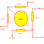
Stepper motors are brush less dc motors. They have coils and permanent magnets which rotate the shaft.There are generally two types of stepper motors categorized on their coil configurations uni polar and bi polar. Uni polar motors have a common signal wire whose signal remains fixed all the time. Bipolar motors are independent from common wire. I am not going to dive deep in the stepper motors difference. Just wrote above the major difference between the two stepper motors.
Stepper motors are brush less dc motors. They have coils and permanent magnets which rotate the shaft.There are generally two types of stepper motors categorized on their coil configurations uni polar and bi polar. Uni polar motors have a common signal wire whose signal remains fixed all the time. Bipolar motors are independent from common wire. I am not going to dive deep in the stepper motors difference. Just wrote above the major difference between the two stepper motors.
Main project
I am going to interface the stepper motor with stm32 microcontroller. My main task is to teach you people how to interface, program and control the stepper motor with stm32f103 microcontroller using stm32cubemx code configurator.
Project hardware
- Stepper motor NEMA 17
- Stm32f103c8t6 microcontroller
- A4988 stepper motor driver
Stepper Motor
For this project i am going to use bipolar stepper motor. The name of motor is NEMA 17. It is commonly used in 3D printers and is popular among diy circuit makers. Its a 2 phase 4 wire stepper motor. It consumes 1 amperes to 1.5 amperes of current. Voltage requirements are 2.4 volts minimum. Step angle is 1.8 degrees. For full 360 degree rotation it takes (360/1.8=200) 200 steps.
A4988 stepper motor driver
Stepper motors sink 1 ampere of current during normal operation. So we need a power supply which can source 1 ampere of continuous current. The old technique is build a H-bridge circuit using transistors or mosfets which can provide sufficient amount of power and can drive motors easily. Making H-bridge circuit is time consuming and takes lot of effort. Luckily now a days their are pre assembled H-bridge drivers available in market which are not only cheap but are also very easy to control. So i decided to use a pre assembled H-bridge circuit in this project. A4988 bipolar stepper motor driver is best suited for our project. A4988 can source 1 amperes to 2 amperes of continuous current at voltages from 8 to 35 volts. It requires 3 to 5 volts for its operation. Pin out and equivalent circuit of the product is below.
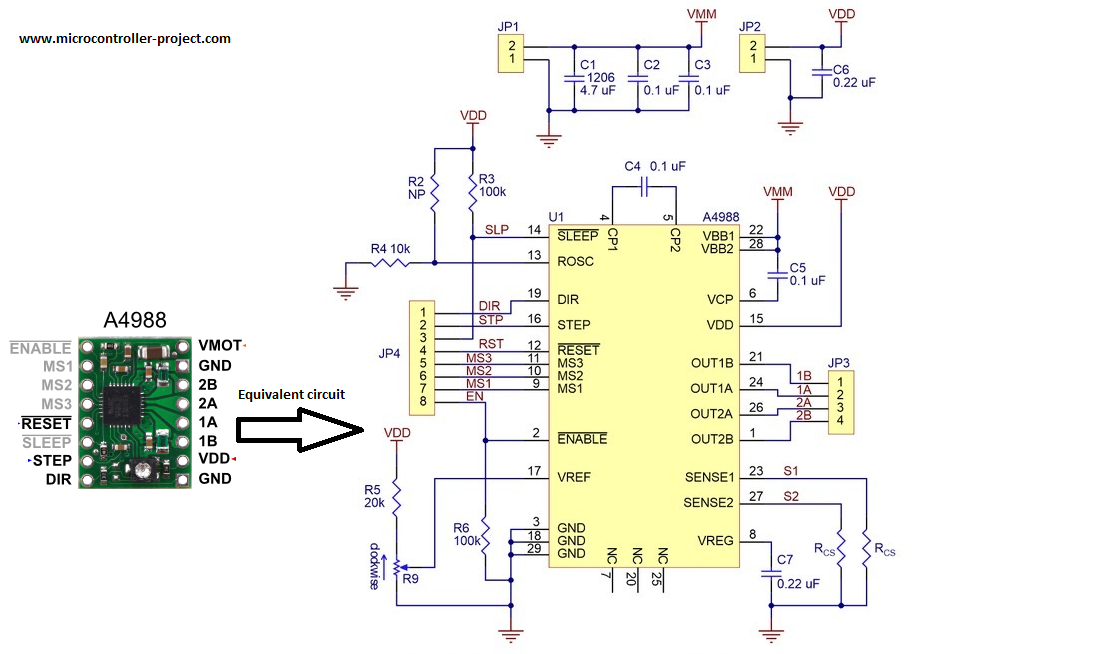
A4988 stepper motor driver equivalent circuit
Apply 3 to 5 volts across VDD and Gnd pins of A4988 motor driver. 1A, 1B, 2A and 2B are output pins. These pins must be correctly connected to 2 phases of bipolar stepper motor. VMOT and GND are power pins connect your power source with them. You can supply 8 to 35 volts across VMOT and GND. When ever a digital square wave signal is applied across the STEP pin stepper motor at output takes one step. DIR pin control the direction of stepper motor. High signal at DIR rotates the shaft of motor in one direction and low at DIR reverses the direction. SLEEP pin takes the module in sleep mode and it stops working. RESET pin brings back the motor to its starting position. Enable pin activates the module. MS1, MS2 and MS3 are steps mode selection pins. By this module we can move the shaft of motor in 5 modes. Resolution modes with settings are given below.
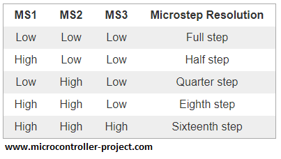
A4988 stepper motor driver resolution control logic
Project circuit
9 volt battery is used to provide power the stepper motor. It is connected between VMOT and GND pins of A4988 stepper motor driver. 100 micro farad capacitor is inserted between the power rails to prevent the power from and AC spike. Nema 17 stepper motor has 4 output pin/wires. Four wires means 2 pair of coils. Each wire has a different color. Normally red and blue is one pair and green and black is another pair. In some motors yellow is used instead of blue and grey is used instead of black. So please be sure first of the coils winding before making any connections. A4988 stepper motor driver is powered with stm32 microcontroller 3.3 volt output power supply. Stm32 also outputs 5 volts. So if you want to power motor driver with 5 volts you can simply change the connection. 3.3 volts worked for me. Reset and Sleep pins are interconnected. Reset pin is a floating pin and Sleep pin is normally pulled up(See the above driver equivalent circuit). So connecting the Reset with Sleep makes Reset pin high, now driver will never reset. Enable pin is left open. It is also internally pulled down which means motor driver is always in enable mode.
I am going to drive the motor in Full step mode. For full step mode you need to make the A4988 stepper motor driver mode pins low. The motor drive mode pins Ms1, Ms2 and Ms3 are untouched. They remained open and works for me. Although it worked for me but i recommend to connect the Ms1,Ms2 and Ms3 to ground for full step mode. Next the Step pin of motor driver is connected to Port-A pin# 4 of stm32f103 microcontroller. Direction pin is connected to Port-A pin#3 of stm32 microcontroller. Circuit diagram of the project is given below.
I am going to drive the motor in Full step mode. For full step mode you need to make the A4988 stepper motor driver mode pins low. The motor drive mode pins Ms1, Ms2 and Ms3 are untouched. They remained open and works for me. Although it worked for me but i recommend to connect the Ms1,Ms2 and Ms3 to ground for full step mode. Next the Step pin of motor driver is connected to Port-A pin# 4 of stm32f103 microcontroller. Direction pin is connected to Port-A pin#3 of stm32 microcontroller. Circuit diagram of the project is given below.
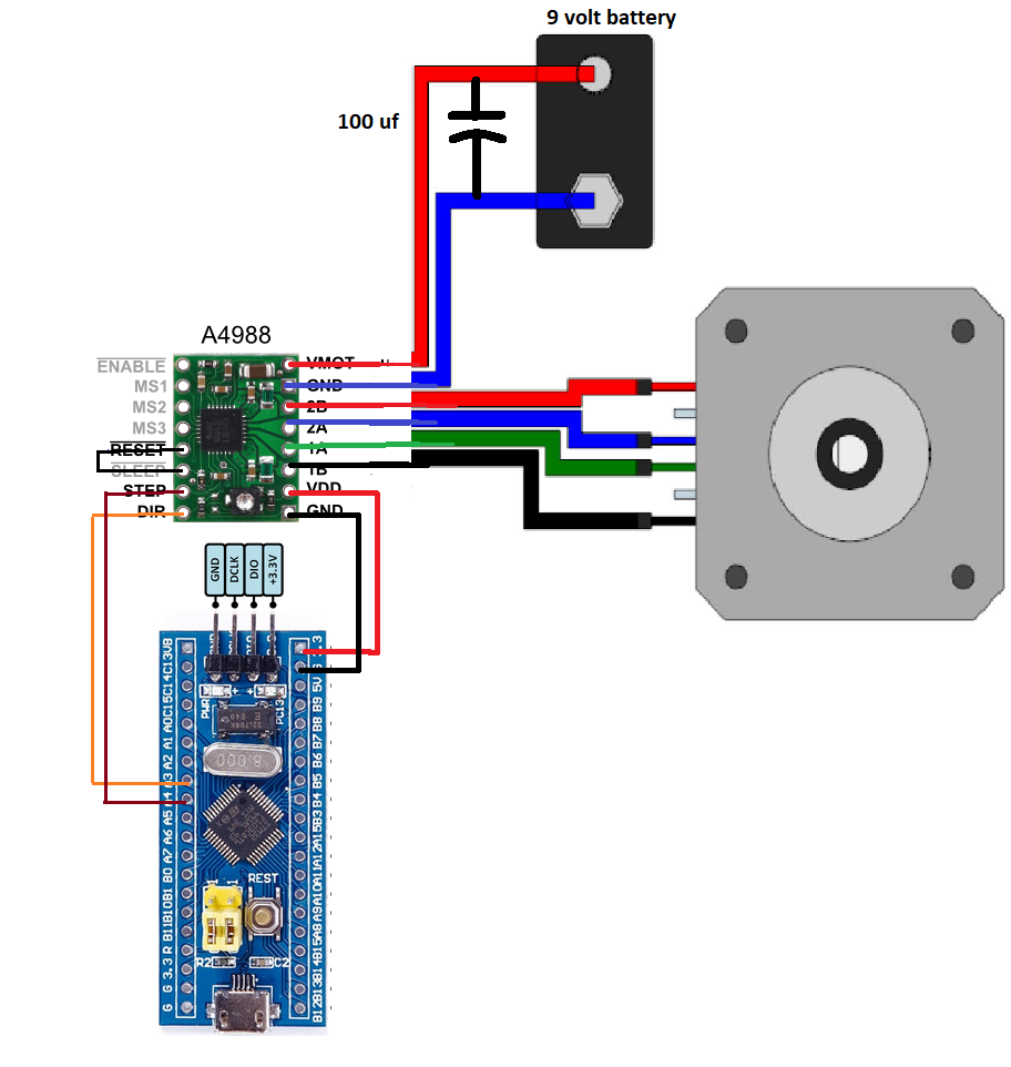
stepper motor nema 17 controlled with stm32 microcontroller
Code of the project is written and compiled in keil arm v5 ide. Stm32cubemx code configurator is used to configure the stm32f103c8t6 settings. Internal hc 8 Mhz oscillator is used to provide the clock source to microcontroller system, buses and other microcontroller peripherals. Two stm32 Port-A pins are declared as output and assigned names. If you are new and don”t have previous experience with Stm32cubemx, keil arm ide then you must take the getting started tutorial. After taking the tutorial you can easily understand the statements of code below. Click the button to take tutorial.
The main logic in the above code is in the while(1) function. First the direction pin is set high. This will set the stepper motor to move in clock wise direction.
HAL_GPIO_WritePin(GPIOA, DIR_Pin, GPIO_PIN_SET);//Clock wise rotation
Then a for loop moves the motor. In for loop steps are provided to motor. Recall nema 17 stepper motor takes 200 steps to take one full 360 degree rotation(Step angle 1.8 degree). So for loop is run for 200 times to complete one rotation. Then the direction pin is made low and now the motor will take steps back word. In this state stepper motor is also taking 200 steps. It comes back to its initial position.
Future work
This tutorial is basic a lesson on how to run stepper motor with stm32 microcontrollers using keil ide and stm32cubemx. For future you can test the stepper motor with micro steps. Change the A4988 modes and test every mode 1/4, 1/8 and 1/16. You can also change the frequency of rotation or control the speed of shaft rotation. Since this tutorial is based on bipolar stepper motor you can test the uni polar motor in future with little modifications in circuit and code.
Download the project code. Folder contains the stm32cubemx and keil arm files. Code is open source. Please provide us your feed back on the project. <! — adsense links> </!>
You may also like:


Filed Under: Electronic Projects, STM32, STM32.

Questions related to this article?
👉Ask and discuss on Electro-Tech-Online.com and EDAboard.com forums.
Tell Us What You Think!!
You must be logged in to post a comment.