This is the one another Article to introduce the programming of ARM Cortex-M3 LPC1768 Microcontroller. Here we are going to do input and output functions of GPIO of LPC1768. For better understanding we are going to use a button and the LED. Our idea is to program in such a way that when the button is pressed, the LED will be ON. Setting up the Environment for the development of ARM cortex M3 is well discussed in this article.
The LPC 1768 is ARM Cortex- M3 based Microcontrollers for embedded application features in low power consumption and a high level of integration. The ARM Cortex M3 is designed in a such way to enhance debug features and a higher level of system integration. It clocks at a CPU frequency of 100 MHz, and incorporates a 3-stage pipeline and uses a Harvard architecture with separate local instruction and data buses for third bus peripherals. The ARM Cortex- M3 CPU have an internal pre-fetch unit to support speculative branching. The peripheral components include 512KB of flash memory, 64kb of data memory, Ethernet MAC, USB OTG, 4 UART’s, 8-channel general purpose DMA controller, 2 SSP Controllers, 10-bit DAC, Quadrature encoder interface, SPI interface, 3 I2C bus interface, 2 input plus 2 outputs I2S bus interface, 4 general purpose timers, ultra-low power Real-Time Clock (RTC) with separate battery supply, and up to 70 general purpose I/O pins, 6-output general purpose PWM. The LPC1768/66/65/64 are pin-compatible with the 100-pin LPC236x ARM7-based Microcontroller series.

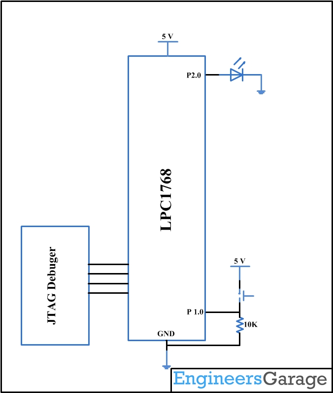
Fig. 1: Switch and Led interface with LPC1768 Prototype
Before entering into the coding of interfacing of the LED and Switch lets have an introduction to the Registers in LPC1768 and its Configuration.
Register Configuration (lpc17xx.h):
As LPC1768 is 32-bit architecture which is memory mapped to the location 0x2009 C000 to 0x2009 FFFF. Special Function registers of LPC1768 are defined in lpc17xx.h which is included in the beginning of the project. There are 5 ports (PORT0 – PORT4). Every PORT will not have 32 physical pins. A structure is defined in the System file LPC_GPIOn(n= 0,1,2,3) contains all the registers for required for GPIO operation. Refer lpc17xx.h file for more info on the registers.
PINSEL: GPIO Pins Select Register:
PINSEL register is to be configured before using the PIN, since almost all the pins has a max of four alternative functions. Below table explains the function for a particular pin using two bits of the PINSEL register.
|
Value |
Function |
Enumeration |
|
00 |
Primary (default) function, typically GPIO port |
PINSEL_FUNC_0 |
|
01 |
First alternate function |
PINSEL_FUNC_1 |
|
10 |
Second alternate function |
PINSEL_FUNC_2 |
|
11 |
Third alternate function |
PINSEL_FUNC_3 |
Fig. 2: Bit Value of PINSEL Register to select GPIO Pins in LPC1768
FIODIR:Fast GPIO Direction Control Register.
This register individually controls the direction of each port pin.
|
Values |
Direction |
|
0 |
Input |
|
1 |
Output |
Fig. 3: Bit Value of FIODIR Register to control diretion of Ports in LPC1768
FIOSET:Fast Port Output Set Register.
This register controls the state of the output pins. Writing 1 produces highs at the corresponding port pins. Writing 0s has no effect. Reading this register returns the current contents of the port output register not the physical port value.
|
Values |
FIOSET |
|
0 |
No Effect |
|
1 |
Sets High on Pin |
FIOCLR:Fast Port Output Clear Register.
This register controls the state of the output pins. Writing 1 produces lows at the corresponding port pins. Writing 0s has no effect.
|
Values |
FIOCLR |
|
0 |
No Effect |
|
1 |
Sets Low on Pin |
Fig. 4: Bit Value of FIOCLR Register to control state of output pins in LPC1768
FIOPIN:Fast Port Pin Value Register.
This register is used for both reading and writing data from/to the PORT.
Output: Writing to this register places corresponding values in all bits of the particular PORT pins.
Input: The current state of digital port pins can be read from this register, regardless of pin direction or alternate function selection (as long as the pins are not configured as an input to ADC).
Note:It is recommended to configure the PORT direction and pin function before using it.
Create a project using Keil uvision4 for LPC1768 Microcontroller:
In this section, we will start creating a project in Keil MDK we have already installed Keil µVision and Co-MDK Plug-in + CoLinkEx Drivers required for the CoLinkEx programming adapter. You can start by downloading the project files and kick start your practical experiment.
Code Description:
ARM programming requires good handling of Bit manipulation in C language. Here is the small note in the introduction of Bit manipulation to a newbie. C has direct support for bitwise operations that can be used for bit manipulation. In the following examples, n is the index of the bit to be manipulated within the variable bit_fld, which is an unsigned char being used as a bit field. Bit indexing begins at 0, not 1. Bit 0 is the least significant bit.
Set a bit
bit_fld |= (1 << n)
Clear a bit
bit_fld &= ~(1 << n)
Toggle a bit
bit_fld ^= (1 << n)
Test a bit
bit_fld & (1 << n)
The LED is connected to the Port 2.0 and the Switch is connected to the Port 1.0, below are code snippets used to make it work.
LPC_GPIO2->FIODIR = 0x000000FF; /* P2.xx defined as Outputs */
LPC_GPIO2->FIOCLR = 0x000000FF; /* turn off all the LEDs */
LPC_GPIO1->FIODIR = 0x00000000; /* P1.xx defined as Inputs */
LPC_GPIO1->FIOCLR = 0x000000FF; /* Make it low */
The above lines are to SET the PORT 2 pins as output and clearing it. LPC_GPIO2 structure consists of FIODIR,FIOCLR and FIOSET members.
switchStatus = (LPC_GPIO1->FIOPIN>>0) & 0x01 ; // Read the switch status
if(switchStatus == 1)
{
LPC_GPIO2->FIOPIN = (1<<0);
}
else
{
LPC_GPIO2->FIOPIN = (0<<0);
}
The above if loop is to check the status of the input pin and accordingly changing the output of the output pin.
You may also like:


Project Source Code
###The codes are linked in Description ###
Circuit Diagrams
Project Components
Project Video
Filed Under: ARM., Tutorials
Filed Under: ARM., Tutorials

Questions related to this article?
👉Ask and discuss on Electro-Tech-Online.com and EDAboard.com forums.
Tell Us What You Think!!
You must be logged in to post a comment.