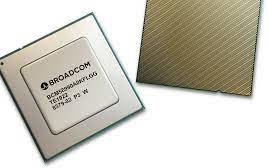
Broadcom Inc. announced delivery of the new Broadcom Trident 4-X7 Ethernet switch ASIC — a 4.0 Terabits/second fully programmable switch designed for enterprise data center ToR (Top of Rack) boxes. The Trident 4-X7 offers native support for 400G connectivity to the next-generation spine/fabric technologies, which are making their way from the cloud into enterprise data…
Broadcom and Arista offer industry’s first open, end-to-end RDMA networking solution
Broadcom Inc. has announced the availability of the industry’s first open end-to-end networking solution optimized for Remote Direct Memory Access (RDMA) over Converged Ethernet. Hyperscaler and enterprise data-center operators can now deploy fully optimized systems that are connected by Broadcom, using open-standard RDMA. Jointly integrated by Broadcom and Arista, this end-to-end solution features Broadcom’s Ethernet…
Microchip enables OEM’s to double router and switch system capacities
The demand for increased bandwidth and security in network infrastructure driven by growth in hybrid work and geographical distribution of networks is redefining borderless networking. Led by AI/ML applications, the total port bandwidth for 400G (gigabits per second) and 800G is forecasted to grow at an annual rate of over 50%, according to 650 Group.…
Infineon offers Press Pack IGBT for transmission and distribution applications
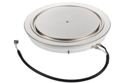
Infineon Technologies Bipolar GmbH & Co. KG has expanded its high-power Prime Switch family with the new Press Pack IGBT (PPI) with internal freewheeling diodes (FWD) in ceramic disc housings. This PPI is specifically designed for transmission and distribution applications and is ideal for high-current Modular Multilevel Converter (MMC), medium-voltage drives, DC breakers, wind-turbine converters,…
Meta deploying world’s highest bandwidth Ethernet switch chip
Broadcom announced that Meta is now deploying the world’s highest bandwidth Ethernet switch chip in its data center network fabric — the Broadcom StrataXGS Tomahawk 4 switch series. A 25.6 Tbps Ethernet switch, the Tomahawk4 is now shipping in high volume in Meta’s Minipack2 platform, which is an industry first. The Tomahawk family has consistently…
New automotive-compliant power switch delivers adjustable current limit
Diodes Incorporated introduces the new, AP22653Q programmable current-limiting power switch. Streamlining power- system design and assuring ongoing reliability, this automotive-compliant device provides a controlled and protected power path. The new power switch is rated to handle continuous load currents of up to 1.5A. Key applications include protection of vehicle USB ports and ECU supply rails,…
Microchip offers first multiport, multigigabit PoE injector for Wi-Fi6 access
To deploy today’s Wi-Fi 6 access points (APs) and 5G small cell access nodes, it’s first necessary to access AC power or a switch that can deliver both power and data as required. Microchip Technology Inc. has created a more flexible and cost-effective alternative with the first multiport Power-over-Ethernet (PoE), power-sourcing equipment (PSE) injector —…
Introduction to Relays
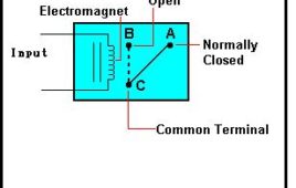
Relay is a very important device now days. They are used in various circuits and many of us have problem of how to use a relay. With the help of this article I have tried to explain two things firstly the Working of relay and secondly how to use a relay. As we know relay is a device which is used to provide connection between two or more points or device in response to the input signal applied. In another words relay provide isolation between the controller and the device as we know devices may work on AC as well as on DC. However, they receive signals from microcontroller which works on DC hence we require a relay to bridge the gap. Relay is extremely useful when you need to control a large amount of current or voltage with small electrical signal.
Switch Status & LED with AVR microcontroller- (Part 6/46)
Generally we know about interfacing button switches, LED with Atmega32 microcontroller. We know that interface switch’s to one port, LED’s to another port and if we press any switch the corresponding LED will glow. But all the LED’s operate with single switch we don’t know. Here we are developing the program for operating 7 LED’s with one switch. The circuit connections and programming is so simple. We will discuss here about that. First we see the circuit connections. Let us take any one port of Atemga32 controller is PortD. Connect 7 LED’s to PortD and connect on switch to remaining pin of the PortD. Now let us start the coding for microcontroller. First open the Atmel Studio software of any version. Create a new project with your desired file name. Here I am taking the project name as “button switch”.
6 Interesting mechanical motion transfer mechanisms you can use in your product design
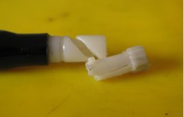
Product designing often involves challenges of transferring mechanical motion between different parts of the product. A product can involve different types of motion like horizontal, vertical, radial, circular, see saw, spiral etc. The product designer’s community has to intelligently deal with parameters like space, cost optimization, strength, user comfort, look and feel etc. A combination of parts and structure designed to perfection work in synchronization to achieve the desired motion.From movement of a ball pen’s tip to the to and fro motion of the switch’s actuator, there is enough science and wonder in exploring designing methods for all mechanical motions. The factor of easiness and simple working is always fulfilled too. How does it all happen? What is the magic? Have a look at some of the common yet unseen mechanics involved in transfer of motion from the brains of product designers.
Toggle switch using CD4017
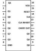
This circuit will help you to control two devices with the help of a switch. If you “on” the first device then second device remain “off”, and if you “on” the second [[wysiwyg_imageupload::]]device the first device will become “off”. Therefore you can control both the devices with the help of single switch. The circuit is built around CD4017 which is a CMOS decade counter/ Divider. Used in many applications like binary counter/decoder, frequency division, divide by N counting, Alarm system etc. CD4017 is a 16 pin IC which includes 3 input- Clock, Reset and Clock inhibit. And 10 output Q0- Q9. Pin 16 is for power supply and pin 8 is used for ground. Read more to find out working of the circuit.
9-Way Clap Switch Circuit Diagram
With the help of this circuit you can control your home appliances without getting off from your bed. You have to just clap or puff in front of the microphone and the device connected to it become “on” or “off”. Features of this circuit are :- You can simultaneously “on” and “off” one, two or three devices.. You are not required to move from your place to “on” or “off” the devices.When you clap in front of the Mic, clapping sound is converted into electrical energy by the microphone. These weak signals are then amplified by the transistor which acts as preamplifier. Sensitivity of the signals can be improved with the help of VR1. Now the transistor T1’s output is feed to monostable circuit which is wired NE555 IC. Whenever you clap in front of microphone, output pin 3 of IC1 goes high and this is fed to clock input of IC2 pin 14.
Wireless Switch Circuit Diagram
Normally, home appliances are controlled by means of switches, sensors, etc. However, physical contact with switches may be dangerous. The circuit [[wysiwyg_imageupload::]]described here requires no physical contact for operating the appliance. You just need to move your hand over the light dependent resistor (LDR). The device connected to it switches “on” when you put your hand over the LDR and remains “on” until you again move your hand over it.The circuit is based on two ICs: one is operational amplifier LM741 and JK Flip Flop CD4027. An op-amp produces an output voltage that is hundreds of thousand times larger than the voltage difference between its input terminals. CD4027 is a master slave JK flip flop IC which works in toggle mode. Here this IC can be used to change the state by the signal applied to one or more control inputs and will have one or two outputs. CD4027 has four inputs namely J, K, Set and Reset and it contain two outputs namely Q and Q bar (Q not).
Sound Operated Switch
Detailed here is a circuit which will switch ON the light by just listening your clap sound. Another advantage of this circuit is that you cannot get any electrical [[wysiwyg_imageupload::]]shock as we did not have to use any mechanical switch.The circuit is based on two IC :operational amplifier LM741 and JK flip-flop based CD 4027.An op-amp produces an output voltage that is hundreds of thousand times larger than the voltage difference between its input terminals .CD4027 is the master slave JK flip flop IC which work in toggle mode. Here, this IC can be used to change the state by signal applied to one or more control inputs and will have one or two outputs. CD4027 has four inputs namely J, K, Set and Reset and it contain two output namely Q and Q bar(Q not).
Dust bot
It is always better to make bots in a set of modules which can be assembled together to form the required bot. For the dust bot there are two things required, first a gripper that can hold the balls and second a vehicle that can take that gripper from one place to another. First of all it is required to make a vehicle that can be controlled by the wired controls. After accomplishing this task we need a mechanism to grab the balls. Further the grip of the grabber should be of such strength that the balls don’t fall of the bot till we reach the finishing end. The movement of the gripper should be bidirectional and quite precise as we require the movement of the gripper in both the directions. The stability is the success of every bot. More the stability in your design better is your bot. Hence, the arm holding the gripper should be properly fixed and shouldn’t be unstable. Therefore, aluminum rods were chosen with clamps for enhanced stability of the gripper. And most important the bot should utilize the off the shelf material and it must be really economic.
Reed Switch: Understanding Specifications
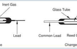
A reed switch consists of two ferromagnetic nickel-iron wires and specially shaped contact blades (reeds) positioned in a hermetically sealed glass capsule with a gap between them and in a protective atmosphere. The glass capsule is filled with inert gas to prevent activation of the contacts. The ruthenium or rhodium plated contact surfaces are isolated from the outside environment, which protects the contacts from contamination. Reed switches can be operated using a magnetic field generated by either a permanent magnet or current-carrying coil. They induce north (N) and south(S) poles on the reeds. The magnetic attractive force leads to closure of the reed contacts. Upon removal of the magnetic field, contact open again due to the elasticity of the reeds. There are Reed Switches which operate with permanent magnet, while there are Reed Switches operate with coils which can be magnetized by sending current through them.
Remote FM Bell (and Switch)
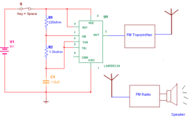
This is very interesting project. It is same as commercial available wireless FM bell but with sweet melody output. It can also be use to operate any AC/DC device from remote and safe place. The range of this remote control is up to 50 meter (basically this depends upon your FM transmitter if you use higher power…
CD 4013 Based Two Way Switch
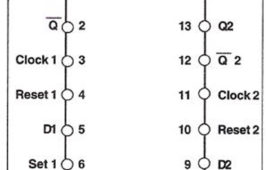
In festival days, we switch ON the lights of our corridor, balconies or staircase. In the case when people have lighting done at two different locations, they have [[wysiwyg_imageupload::]]to go to two different places to switch ON the light but, with the help of this circuit, you can switch ON both the lights with a simple touch. This simple circuit is built around CD4013 which has two independent flip flops on a single chip and each module is further equipped with a group of pin outs assigned as data, set, reset, clock input and a couple complementary output Q and NOT Q. CD4013 is a 14 pin IC which contains two independent sets of flip flops and in our circuit we are utilizing both. Read on more to find out how the circuit is made and how it works.
Flip Flop based Staircase Switch
In many cases, the stairs have a power switch at the bottom which is often left switched on during night. No one wants to go down to switch it off and hence, [[wysiwyg_imageupload::]]unnecessary on, it leads to wastage of electricity.To solve this problem we have described a simple circuit which contains two micro switches; one at the top and other located at the bottom of the staircase that can be pushed and released easily during climb-up from the bottom of the staircase or climb-down from the top of staircase. In short you can use any switch to on and off the light.This simple circuit is built around a CD4013 IC which has two independent D type flip flops which exist in complimentary states and can store information. Each module is further equipped with a group of pin outs assigned as data, set, reset, clock input and a couple complementary output Q and Not Q.
Insight – How Micro Switch Works
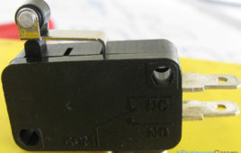
A micro switch, also known as miniature snap action switch, is a type of momentary contact switch used widely in automotive, industrial and medical instruments as sensor. The switch is termed as “micro” on the name of the company who first started manufacturing it commercially. The actuator of these switches often has a hinged wheel placed above a push button. This switch is widely used in control system applications such as a door interlock, safety switches in elevators, vending machines etc. Having a diverse range of engineering applications, micro switches are available in various switch configurations, housing materials, actuator styles etc.

