There are 2 cut off frequencies for band reject filter. First is the upper cut off frequency (f1) -which is the frequency below which all the frequencies are passed. The second is the lower cut off frequency (f2) – which are all the frequencies above this frequency are passed.Similar to band pass filter but the difference is f1 < f2. That means upper cut off frequency is lesser than lower cut off frequency. Two types of band reject filters are
Insight – How Dynamic Microphone Works
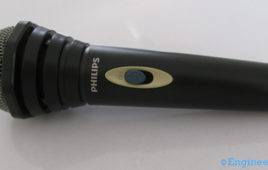
How loud can you shout to make yourself heard at a distance? How large is that distance? A hundred meters, a kilometer, is that it? What if you were to talk to peopleseparated by miles, could you shout that loud and kill your lungs? Or you’d rather whisper into an adjacent ear, and be heard at some other location, no matter the distance, and perhaps irrespective of time? An electronic ear that couldhelp store and transmit your voice and sound at light speeds and even ramp it up if you are too frail? Yes, such is the microphone!But how does a microphone achieve such a feat? How does it follow our rhythmic and unpredictable sounds and change them into electrical signals?Let us find out how by peering into one such device, the dynamic microphone.
Basic high Pass Filter Circuit using capacitor and resistor
A high pass filter is just opposite to a low pass filter. It is employed to avoid or retain frequencies which are lower than filter’s cutoff frequency. It is also [[wysiwyg_imageupload::]]known as low-cut filter since it provides a difficult passage to low frequency signals from source to output. High pass filters find their applications in multimedia circuits such as audio tweekers etc. Also, the concept of high pass filtering is used in digital signal processing of images and animated data.It is, however, pretty interesting to know that a low pass filter can be converted to high pass and vice versa just by shuffling the combination of resistance and capacitance. The cutoff frequency is the design parameter of the filter and depends on the value of capacitor C and resistor R according to the relation f = ½(pi)RC. Let’s make an interesting circuit project on high pass filter.
Basic low pass filter using capacitor and resistor
To avoid unwanted noise in the output, a filter is required to be placed before it. Such filters are more commonly used in audio circuits. To avoid or retain [[wysiwyg_imageupload::]]frequencies which are higher than filter’s cutoff frequency, a low pass filter is employed. The low pass filter circuit which is the prime part of this project, filters a frequency spectrum or any mix of frequencies. It is also known as high-cut filter since it provides a difficult passage to high frequency signals from source to output as shown in this project. Low pass filter is used for signal decoding, audio amplifiers, and demodulators. Also, various consumer electronic gadgets like mobiles, speakers system, gaming consoles, digital image display units apply a low pass filter.
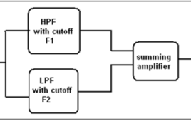
Designing a band pass filter
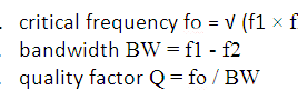
There are 2 cut off frequencies for band pass filter.1. upper cut off frequency (f1) – the frequency below which all the frequencies are passed2. lower cut off frequency (f2) – all the frequencies above this frequency are passedFrom this f1 and f2 we shall define following parameters which are designing parameters for band pass filter.
Designing of High Pass Filter

Higher order filters like 3rd, 4th or 5th order filters can be designed by cascading 1st order and 2nd order LPF sections. Increasing order increases stop band attenuation by 20 db. The figure given below gives better idea. So using higher order filter we can get better response with stiff slop. We may get response like idle LPF.