This Project is submitted by Mr. Saif Ullah Qureshi from UET,Lahore, Pakistan
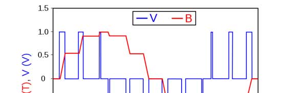
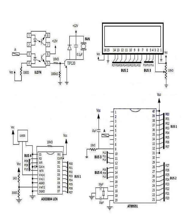
A simple project using microcontroller AT89S51 to control the speed of 12V fan according to the surrounding temperature. In this project we use the concept of PWM (pulse width modulation) to increase or decrease the speed of fan. We also interface 2*16 characters LCD which shows the outside temperature through the temperature sensor. Followings are the details of the project.
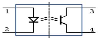
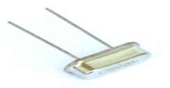
Components Description
Project Source Code
###
ORG 0H
LJMP STRT
ORG 000BH
LJMP INTRR
ORG 0030H
STRT:
SETB P1.5
MOV P0,#0FFH
PL: SETB P3.5
SETB P3.3
CLR P3.4
SETB P3.4
H9: JB P3.5,H9
CLR P3.3
LCALL INI
MOV A,#'M'
ACALL DWRO
ACALL DE
MOV A,#'I'
ACALL DWRO
ACALL DE
MOV A,#'C'
ACALL DWRO
ACALL DE
MOV A,#'R'
ACALL DWRO
ACALL DE
MOV A,#'O'
ACALL DWRO
ACALL DE
MOV A,#'C'
ACALL DWRO
ACALL DE
MOV A,#'O'
ACALL DWRO
ACALL DE
MOV A,#'N'
ACALL DWRO
ACALL DE
MOV A,#'T'
ACALL DWRO
ACALL DE
MOV A,#'R'
ACALL DWRO
ACALL DE
MOV A,#'O'
ACALL DWRO
ACALL DE
MOV A,#'L'
ACALL DWRO
ACALL DE
MOV A,#'L'
ACALL DWRO
ACALL DE
MOV A,#'E'
ACALL DWRO
ACALL DE
MOV A,#'R'
ACALL DWRO
ACALL DE
MOV A,#0C4H
ACALL CW
ACALL DE
MOV A,#'P'
ACALL DWRO
ACALL DE
MOV A,#'R'
ACALL DWRO
ACALL DE
MOV A,#'O'
ACALL DWRO
ACALL DE
MOV A,#'J'
ACALL DWRO
ACALL DE
MOV A,#'E'
ACALL DWRO
ACALL DE
MOV A,#'C'
ACALL DWRO
ACALL DE
MOV A,#'T'
ACALL DWRO
ACALL DE
ACALL DELAY
MOV A,#01H
ACALL CW
ACALL DE
MOV A,#'T'
ACALL DWRO
ACALL DE
MOV A,#'E'
ACALL DWRO
ACALL DE
MOV A,#'M'
ACALL DWRO
ACALL DE
MOV A,#'P'
ACALL DWRO
ACALL DE
MOV A,#' '
ACALL DWRO
ACALL DE
MOV A,#'C'
ACALL DWRO
ACALL DE
MOV A,#'O'
ACALL DWRO
ACALL DE
MOV A,#'N'
ACALL DWRO
ACALL DE
MOV A,#'T'
ACALL DWRO
ACALL DE
MOV A,#'R'
ACALL DWRO
ACALL DE
MOV A,#'O'
ACALL DWRO
ACALL DE
MOV A,#'L'
ACALL DWRO
ACALL DE
MOV A,#' '
ACALL DWRO
ACALL DE
MOV A,#'F'
ACALL DWRO
ACALL DE
MOV A,#'A'
ACALL DWRO
ACALL DE
MOV A,#'N'
ACALL DWRO
ACALL DE
MOV A,#0C6H
ACALL CW
ACALL DE
MOV TMOD,#02H
MOV IE,#82H
MOV R1,P0
MOV A,R1
MOV R4,A
ACALL COMPAIR
MOV A,R4
LCALL CONV
LCALL DTA
ACALL DELAY
LJMP STRT
DELAY:
MOV R3,#0FFH
H12: MOV R5,#0FFH
H11: MOV 73H,#01FH
H13: DJNZ 73H,H13
H14: DJNZ R5,H11
DJNZ R3,H12
RET
COMPAIR:
CLR C
CJNE R1,#30,A4
A4: JNC A3
CLR C
CJNE R1,#25,A5
A5: JNC A2
CLR TR0
LJMP A1
A3: ACALL GRAT
SJMP A1
A2: ACALL LOWER
A1: CLR C
RET
CW:
MOV P2,A
CLR P3.1
CLR P3.0
SETB P3.2
ACALL DE
CLR P3.2
RET
DWRO:
MOV P2,A
SETB P3.1
CLR P3.0
SETB P3.2
ACALL DE
CLR P3.2
RET
DE:
MOV R3,#0FFH
H1: DJNZ R3,H1
RET
INI: MOV A,#38H
ACALL CW
ACALL DE
MOV A,#0EH
ACALL CW
ACALL DE
MOV A,#01H
ACALL CW
ACALL DE
MOV A,#06H
ACALL CW
ACALL DE
MOV A,#081H
ACALL CW
ACALL DE
RET
DTA:
MOV A,R6
ACALL DWRO
ACALL DE
MOV A,R7
ACALL DWRO
ACALL DE
MOV A,#'C'
ACALL DWRO
ACALL DE
RET
CONV:
MOV B,#10
DIV AB
MOV R7,B
MOV B,#10
DIV AB
MOV R6,B
MOV A,R6
ADD A,#30H
MOV R6,A
MOV A,R7
ADD A,#30H
MOV R7,A
RET
INTRR:
CPL P1.5
CLR TR0
MOV 79H,R2
HE: DJNZ 79H,HE
SETB TR0
CPL P1.5
RETI
GRAT:
CLR TR0
MOV R2,#0AAH
MOV TH0,#0AFH
SETB TR0
RET
LOWER:
CLR TR0
MOV R2,#0AAH
MOV TH0,#1FH
SETB TR0
RET
END
###
Circuit Diagrams
Filed Under: Electronic Projects

Questions related to this article?
👉Ask and discuss on Electro-Tech-Online.com and EDAboard.com forums.
Tell Us What You Think!!
You must be logged in to post a comment.