Engineers Garage

  • Projects and Tutorials
    • Electronic Projects
      • 8051
      • Arduino
      • ARM
      • AVR
      • PIC
      • Raspberry pi
      • STM32
    • Tutorials
    • Circuit Design
    • Project Videos
    • Components
  • Articles
    • Tech Articles
    • Insight
    • Invention Stories
    • How to
    • What Is
  • News
    • Electronic Products News
    • DIY Reviews
    • Guest Post
  • Forums
    • EDABoard.com
    • Electro-Tech-Online
    • EG Forum Archive
  • Digi-Key Store
    • Cables, Wires
    • Connectors, Interconnect
    • Discrete
    • Electromechanical
    • Embedded Computers
    • Enclosures, Hardware, Office
    • Integrated Circuits (ICs)
    • Isolators
    • LED/Optoelectronics
    • Passive
    • Power, Circuit Protection
    • Programmers
    • RF, Wireless
    • Semiconductors
    • Sensors, Transducers
    • Test Products
    • Tools
  • EE Resources
    • DesignFast
    • LEAP Awards
    • Oscilloscope Product Finder
    • White Papers
    • Webinars
  • EE Learning Center
    • Design Guides
      • WiFi & the IOT Design Guide
      • Microcontrollers Design Guide
      • State of the Art Inductors Design Guide
  • Women in Engineering

Timely Beeper

By Ashutosh Bhatt


You can fix this circuit in the switch board that provides power to the loads such as Water heater, Electric Iron etc to remind you that the load is switched on. LED blinks indicating the load on status and the buzzer beeps every 30 minutes. This helps to prevent the wastage of energy usually happens when we forget to switch off these devices. This can be also used to remind, if remote lights such a terrace light is switched on unnoticed.

 
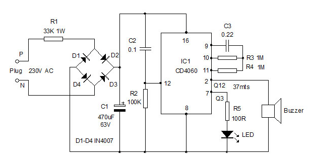
To make the circuit a compact one to enclose inside the switch board, a Resistor based transformerless power supply is used. The 1 watt 33 K resistor reduces the high volt AC to low volt AC which is rectified by the full wave rectifier comprising D1 through D4. Rectified DC is made ripple free by C1so that around 9 volts DC will be available to power the circuit. CD 4060 works safely between 5-18 volts DC and the rectified DC to IC1 is less than 9 volts in normal condition and will not destroy the device unless resistor R1 fails. 
If loud beep is required, use a driver transistor for the buzzer. 
Timely Beeper Circuit2
The timer circuit is built around the popular binary counter IC CD4060 which resets through C2and R2 at power on and starts oscillating with the components C3 and R3. IC 4060 is an Oscillatorcum binary counter cum frequency divider. Its inbuilt oscillator is based on three inverters. The basic frequency of the internal oscillator is determined by the value of the capacitor connected to its pin 9 and that of the resistor in its pin 10. Each output goes high after the completion of the timing cycle.
To get maximum time period output Q10 is omitted in the IC itself so that double time is available between Q9 and Q11. Inside the IC there is an oscillator and 14 seriesconnected bistables (Ripple cascade arrangement). Internally the oscillator signal is applied to the first bistable which drives the second bistable and so on. Since each bistable divides its input signal by two, a total of fifteen signals are available, each of half the frequency of the previous one. Ten of these fifteen signals are available on the output pins Q3- Q13.
 

Timely Beeper

 
With 0.22 capacitor and 1M resistor, the time delay will be approximately:
Pin 3 Q3 4Sec
Pin5 Q4 8 Sec
Pin4 Q5 16 Sec
Pin6 Q6 32 Sec
Pin14 Q7 1 Minute
Pin13 Q8 2 Minute
Pin15 Q9 4 Minute
Pin1 Q11 18 Minute
Pin2 Q12 36 Minute
Pin3 Q13 72 Minute
Circuit 3
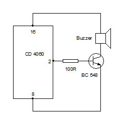
In the circuit LED is connected to the first output Q3 so that it blinks at an interval of 4 seconds. After 30- 37 minutes (slightly affects if the input voltage drops) Pin 2 (Q12) turns high and buzzer beeps. Beep continues for 30 minutes so that ,we will get attention to switch off the load.
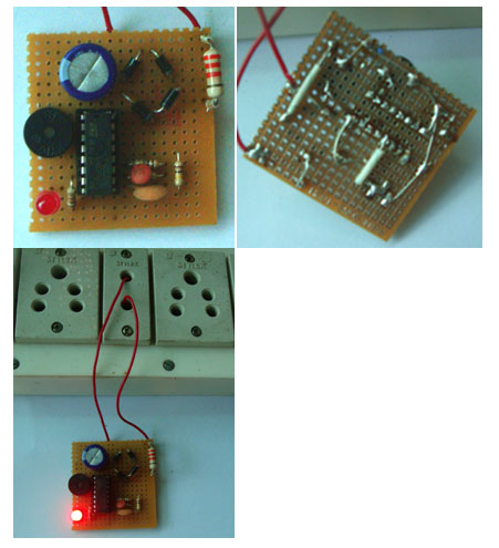
Enclose the circuit in a small plastic case and fix it inside the switch board. Power can be tapped from the Phase and Neutral contacts of the Plug to which the load is connected. So that when the plug switch is turned on, both the load and the beeper circuit gets power.
CD 4060 gives sufficient output voltage and current to drive LEDs and low volt buzzers. So the brightness of LED will be high and beeps from the buzzer will be loud.
 
33 K resistor will heat up slightly and if the heat is too high (check only after removing from AC lines) use 2 watt resistor. Since the circuit turns on only along with the load, it will not cause much problems.
 
Caution: The circuit is connected to the high volt AC directly and there is no galvanic isolation between the hot line and the circuit. So there is risk of Shock if handled carelessly. Do not touch or trouble shoot the circuit when it is connected to mains.


Circuit Diagrams

Timely-Beeper-Circuit_0


Filed Under: Electronic Projects


Questions related to this article?
👉Ask and discuss on Electro-Tech-Online.com and EDAboard.com forums.


Tell Us What You Think!! Cancel reply

You must be logged in to post a comment.

HAVE A QUESTION?

Have a technical question about an article or other engineering questions? Check out our engineering forums EDABoard.com and Electro-Tech-Online.com where you can get those questions asked and answered by your peers!


Featured Tutorials

  • PS2 Keyboard To Store Text In SD Card Using Arduino Circuit Setup On Breadboard
    How To Use PS2 Keyboard To Store Text In SD Card Using Arduino- (Part 42/49)
  • Wireless Path Tracking System Using Mouse, XBee And Arduino Circuit Setup On Breadboard
    How To Make A Wireless Path Tracking System Using Mouse, XBee And Arduino- (Part 43/49)
  • How to Make a Wireless Keyboard Using Xbee with Arduino- (Part 44/49)
  • Making Phone Call From GSM Module Using Arduino Circuit Setup On Breadboard
    How to Make Phonecall From GSM Module Using Arduino- (Part 45/49)
  • How to Make a Call using Keyboard, GSM Module and Arduino
    How To Make A Call Using Keyboard, GSM Module And Arduino- (Part 46/49)
  • Receiving SMS Using GSM Module With Arduino Prototype
    How to Receive SMS Using GSM Module with Arduino- (Part 47/49)

Stay Up To Date

Newsletter Signup

Sign up and receive our weekly newsletter for latest Tech articles, Electronics Projects, Tutorial series and other insightful tech content.

EE Training Center Classrooms

EE Classrooms

Recent Articles

  • Renesas delivers intelligent sensor solutions for IoT applications
  • Microchip Technology releases AVR-IoT Cellular Mini Development Board
  • Qualcomm acquires Cellwize to accelerate 5G adoption and spur infrastructure innovation
  • MediaTek’s chipset offers high-performance option for 5G smartphones
  • Nexperia’s new level translators support legacy and future mobile SIM cards

Most Popular

5G 555 timer circuit 8051 ai Arduino atmega16 automotive avr bluetooth dc motor display Electronic Part Electronic Parts Fujitsu ic infineontechnologies integratedcircuit Intel IoT ir lcd led maximintegratedproducts microchip microchiptechnology Microchip Technology microcontroller microcontrollers mosfet motor powermanagement Raspberry Pi remote renesaselectronics renesaselectronicscorporation Research samsung semiconductor sensor software STMicroelectronics switch Technology vishayintertechnology wireless

RSS EDABOARD.com Discussions

  • lna+mixer noise figure problem
  • Using LTspice to check Current sense transformer reset?
  • Reference driver for negative/above rail voltages.
  • SMPS topology 24v 10A (prefer simplicity, cost-effective, and high efficiency)
  • Thermal pad construction on pcb

RSS Electro-Tech-Online.com Discussions

  • Identify a circuit.
  • How is this tester made?
  • undefined reference header file in proteus
  • Capacitor to eliminate speaker hum
  • Control Bare LCD With ATmega328p
Engineers Garage
  • Analog IC TIps
  • Connector Tips
  • DesignFast
  • EDABoard Forums
  • EE World Online
  • Electro-Tech-Online Forums
  • Microcontroller Tips
  • Power Electronic Tips
  • Sensor Tips
  • Test and Measurement Tips
  • 5G Technology World
  • About Us
  • Contact Us
  • Advertise

Copyright © 2022 WTWH Media LLC. All Rights Reserved. The material on this site may not be reproduced, distributed, transmitted, cached or otherwise used, except with the prior written permission of WTWH Media
Privacy Policy | Advertising | About Us

Search Engineers Garage

  • Projects and Tutorials
    • Electronic Projects
      • 8051
      • Arduino
      • ARM
      • AVR
      • PIC
      • Raspberry pi
      • STM32
    • Tutorials
    • Circuit Design
    • Project Videos
    • Components
  • Articles
    • Tech Articles
    • Insight
    • Invention Stories
    • How to
    • What Is
  • News
    • Electronic Products News
    • DIY Reviews
    • Guest Post
  • Forums
    • EDABoard.com
    • Electro-Tech-Online
    • EG Forum Archive
  • Digi-Key Store
    • Cables, Wires
    • Connectors, Interconnect
    • Discrete
    • Electromechanical
    • Embedded Computers
    • Enclosures, Hardware, Office
    • Integrated Circuits (ICs)
    • Isolators
    • LED/Optoelectronics
    • Passive
    • Power, Circuit Protection
    • Programmers
    • RF, Wireless
    • Semiconductors
    • Sensors, Transducers
    • Test Products
    • Tools
  • EE Resources
    • DesignFast
    • LEAP Awards
    • Oscilloscope Product Finder
    • White Papers
    • Webinars
  • EE Learning Center
    • Design Guides
      • WiFi & the IOT Design Guide
      • Microcontrollers Design Guide
      • State of the Art Inductors Design Guide
  • Women in Engineering