Universal stepper motor speed controller
Stepper motor is a digital motor. It rotates as per applied pulses. The pulses have to be applied in specific sequence to motor coil terminals. The speed of motor can be varied by varying the frequency of applied pulses. As the frequency is increased the speed is increased and vice versa. Increasing frequency means decreasing time period – delay of applied pulses. So as the time period of pulses is decreased the speed of motor increases and vice versa. The maximum frequency (means minimum time period) at which the pulses should be applied depends upon the maximum RPM of motor.

Fig. 1: Prototype of 8051 Microcontroller based Universal Stepper Motor Speed Controller
The project given here demonstrates how to vary speed of any 6-wire or 5-wire unipolar stepper motor. The given circuit can control speed of any unipolar stepper motor having maximum voltage upto 100 V and current upto 5 A. The circuit uses NPN Darlington transistor TIP122 to drive stepper motor that is capable to handle 100 V @ 5A. The circuit is build using AT89C52 micro controller that varies frequency of applied pulses to vary motor speed from min to max. It also uses LCD to display motor speed from 10% to 100%.
Description :
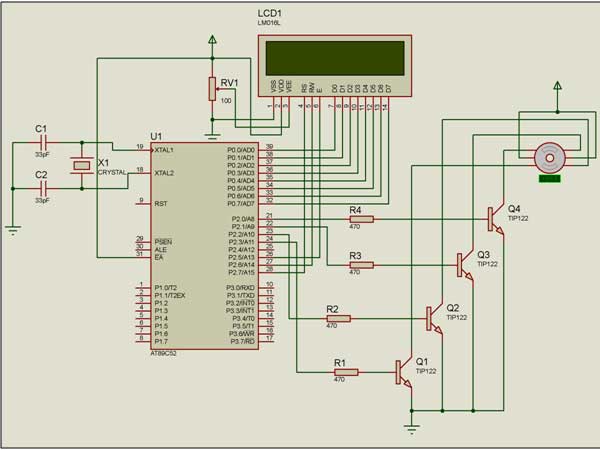
As shown in figure the circuit is built using micro controller AT89C52, LCD and Darlington transistor TIP122.
• Stepper motor is connected to port P2 pins. Port P2 pins P2.0 to P2.3 drives stepper motor through 4 Darlington amplifiers. P2 pins are given to base input of TIP122 and collectors of TIP122 are connected to coil terminals of stepper motor. Two common terminals of stepper motor are shorted and connected to Vcc
• LCD is connected to port P0 and P2 pins. Port P0 drives data pins D0 – D7 of LCD and port P2 pins P2.7, P2.6 and P2.5 are connected to LCD control pins Rs, RW and En pins. One pot is connected to Vee pin as shown to vary brightness of LCD
• A 12 MHz crystal with two 33 pF capacitors is connected to crystal input pins to generate required clock signal
Operation :
• Initially the motor is stop. First the message is displayed on LCD as “stepper motor speed control”
• Then motor starts rotating at very low speed and the motor speed is displayed on LCD as 10%
• The motor rotates at this speed for 5 sec only. After 5 sec motor speed automatically increases to 20%
• The internal timer generates interrupts after every 50 ms. So when 100 such interrupts are counted it means 50×100 = 5000 ms = 5 sec
• So when 5 sec time period is over the delay given between pulses to motor is decreased by 5 ms. So PRF (pulse repetition frequency) is increase so motor speed is increased
• Again after 5 sec, delay is further decreased by 5 ms. So speed is further increased by 10%
• Thus after every 5 sec speed is increased by 10% and that is displayed on LCD as 20%, 30%, 40 % and likewise.
• Speed is increased up to 100% and again it is set to 10%
• The delay is set to 40 ms and decreased to 4 ms. It is set as per maximum RPM of motor. Maximum RPM of motor is 75.
• If motor RPM is more we can decrease the delay further to 2 ms or 1 ms.
Software program :
The program downloaded into internal flash of AT89C52 performs following tasks
• Displays motor speed on LCD in % from 10% to 100%
• After every 5 sec decreases the time period of applied pulses
• Applies pulses in sequence to rotate motor in clockwise direction
The program is written in C language. It is compiled using KEIL (IDE). It consists of following functions
LCD handling functions
• lcd_delay() – gives delay to LCD before data of command given to it
• writecmd() – sends command to LCD to configure it to initializes it
• writedata() – sends data to LCD that is to be displayed
• init_lcd() – initialize LCD to 8 bits / char, 7×5 dots / char
display_speed() function – displays motor speed from 10% to 100% on LCD
delay() function – it generates variable delay in millisecond as per the value passed to it. The delay is
varied from 4 ms to 40 ms
timer0_ISR() function – its timer 0 overflow interrupt function. It counts timer 0 overflow. Timer 0 will overflow after every 50 ms. When count reaches to 100 it gives 100×50 = 5000 ms = 5 sec time. So after every 100 counts the delay (time period) of applied pulses is decreased by 4 ms so motor speed is increased by 10%.
Circuit Diagrams
Project Video
Filed Under: Electronic Projects
Filed Under: Electronic Projects

Questions related to this article?
👉Ask and discuss on EDAboard.com and Electro-Tech-Online.com forums.
Tell Us What You Think!!
You must be logged in to post a comment.