As the name indicates, these kinds of connectors are used to connect a wire or a bunch of wires to a circuit board. There are wide varieties of wire-to-board connectors available. We will be discussing about the PCB Terminal Block, FFC connectors, IDC connectors and RMC connectors
PCB TERMINAL BLOCK
PCB Terminal block is used to terminate the wire at the PCB. These connectors are used only for supply power to or from the PCB. They are little used for transferring signals.

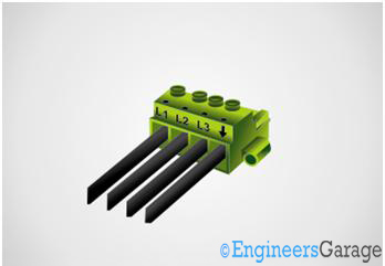
Fig. 1: Image of PCB Terminal Block
One side of the PCB Terminal Block has slots available to insert wire into it and tighten by screws ensuring proper contact. A single slot is normally used for connecting only a single wire, but one can easily connect multiple wires at also. A PCB Terminal Block has at least two wire slots, and there are PCB Terminal Blocks available with more than 10 connection slots.

Fig. 2: Image showing wires connected into PCB Terminal Block
The above image shows how wires can be connected to the PCB Terminal Block. A small part of the insulation of the wire just enough to be fit into the slot is stripped out and can be inserted into the connector. The wire is then safely fixed inside it by tighten down the screw. Each wire has its entry slot into the connector.
The PCB Terminal Block as its name indicates finds its application in almost all kind of PCBs including microcontroller boards.
Sample specification:
Current rating ——————— 15 Amperes
Voltage rating ——————— 300 V
FFC Connectors
FFC CONNECTORS
Flat Flexible Cables (FFC) is used in situations where there are a large number of wires to be connected between two boards or between two sections of a single board unit etc. These cables are very thin and flat. They are made of very flexible plastic with flat copper lines embedded between the plastic layers

Fig. 3: Image of Flat Flexible Cables (FFC)
FFCs are use in standard board design to carry data or signals from board to board or from one section of a board to other since 1970s. FFC connectors are specially designed connectors for connecting the FFC cables to the PCB.

Fig. 4: Image of FFC connectors
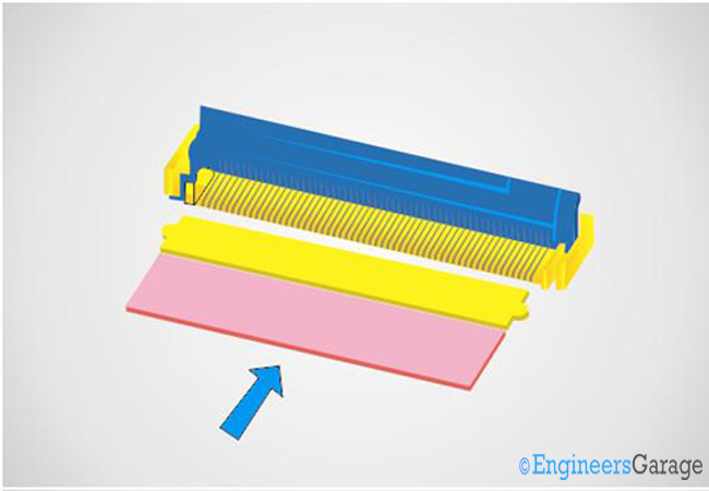
Unlike other connectors there is no crimping or stripping required attaching the FFC to the connector. It has a lock like structure; you can see it in the above image as a black plastic strip. All you need to do is to insert the FFC into the connector and press the lock down.
Fig. 5: Image showing the FFC cables inserted into FFC connector

Fig. 6: Image showing locking of the FFC
The FFC connectors are also referred to as Flat Panel Cable (FPC) connectors. The following image shows a FFC cable connected to a circuit board using the FFC connector.

Fig. 7: Image showing FFC connector connecting FFC to a PCB
Since FFC connectors are widely used in PCB, they can be considered as a component in the PCB design itself. Similar to all other components, the FFC connectors are also available in through hole and SMD models.

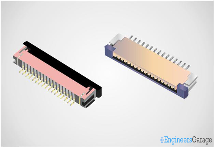
Fig. 8: Image showing FFC through hole and FFC SMD connectors
The above image shows diagram of the bend and straight type FFC connectors in its through hole model and SMD models. The SMD models are used in advanced board and most of them have very small mating cycles.
The FFC connectors find its application high end circuits, embedded system including mobile phones where this FFC connector is always used to connect the wires to the LCD screen.
Sample specification:
Insulation resistance ——————— 500M ohms
Withstanding voltage ——————– 150V AC/1 minute
Contact resistance ———————— 50m ohms
IDC Connectors
IDC CONNECTOR
Insulation Displacement Connector (IDC) is a connector which uses a method called insulation displacement to make the wires connected to the contacts of the connector perfectly. This connector is specifically designed to be used with ribbon type cables.
Ribbon cable is also a kind of flat cable with many actual cables attached side by side forming a single flat wide and flexible cable.

Fig. 9: Image of Flat Ribbon cables
IDC connector is otherwise called referred to as Insulation Displacement Termination (IDT). Unlike other wire terminals there is no need to strip out the insulation of the wire before attaching it to the connector.
Fig. 10: Image of Male and Female IDC connector
The IDC connector has selectively sharpened blade or blades each of them can pierce through the insulation of the corresponding wires in a cable.
 Fig. 11: Image showing sharpened blades in an IDC connector
The wires are inserted into the IDC connector and crimped carefully to ensure perfect connection. A crimping tool can be used for this purpose. The following image might give you an idea about assembly of an IDC connector.

Fig. 12: Image showing IDC connector assembly
It is actually a great advantage; imagine how long it will take to strip all the separate wires in a thirty or forty wire ribbon cable. There is no need of soldering also. Thus the IDC connectors provide easy and highly reliable connection with a ribbon cable.
The IDC connectors are usually found in PCs, low current circuit boards, telecoms devices etc.
Sample specification:
Current rating —————————— 1 ampere
Withstanding voltage ——————– 1050 DC or AC peak
Insulation resistance ——————— >1000 mega ohms
RMC Connectors
RMC CONNECTOR
Relimate Connector (RMC) is another widely used connector in electronic circuit boards. It is also used to connect many wires each to their corresponding connecting points at once.
The wires attached to this connector looks like ribbon cable, but they are completely physically separated from each other. The wires are attached to the male connector by crimping them into the metal plates which sits inside the slots of the outer plastic.

Fig. 13: Image of Male and Female Relimate connectors

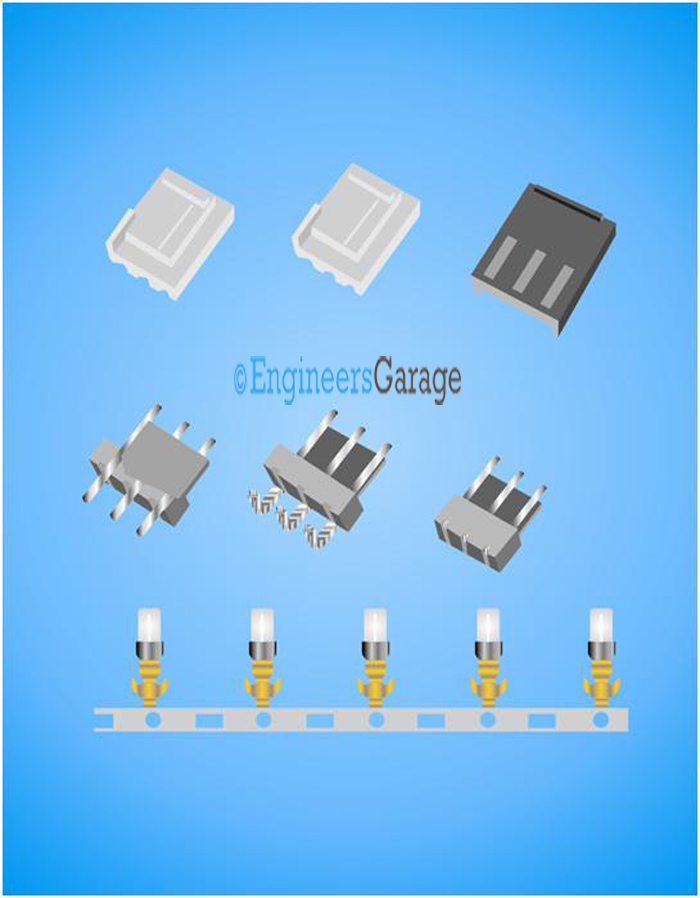
Fig. 14: Image of Relimate connector parts
The metal strip shown in the third row of the above image is cut off into individual pieces and wires are crimped into them. Then they are inserted into the slots of the Relimate connector. The male and female connectors are polarized, means they have matching projections on them which allows them to be connected in only a single orientation. This completely avoids wrong connections which may damage the unit.
They are applied in almost all kind of circuit boards especially in relay boards, PCs as connectors to DVD drive, Hard disk drives etc. They are mainly used to transmit power rather than data or signals.
Sample specification:
Current rating —————————— 3 ampere
Voltage rating —————————— 250 V
Summary
{C}{C}{C}{C}{C}{C}{C}{C}· {C}{C}{C}{C}{C}{C}{C}{C}Wire-to-board connectors are used to connect a wire to circuit board
{C}{C}{C}{C}{C}{C}{C}{C}· {C}{C}{C}{C}{C}{C}{C}{C}The commonly used wire-to-wire connectors are PCB Terminal block, FFC, IDC and RMC
{C}{C}{C}{C}{C}{C}{C}{C}· {C}{C}{C}{C}{C}{C}{C}{C}PCB Terminal Block and RMC are used only for transmitting power or very low frequency signals
{C}{C}{C}{C}{C}{C}{C}{C}· {C}{C}{C}{C}{C}{C}{C}{C}FFC is generally used for transmitting data and usually found in advanced circuit boards, LCD panels etc.
Filed Under: Tutorials


Questions related to this article?
👉Ask and discuss on EDAboard.com and Electro-Tech-Online.com forums.
Tell Us What You Think!!
You must be logged in to post a comment.