It is common to use display screens at railway stations, airports, bus stands and other public places to show messages or alerts. Like at railway station, display boards are installed at the platform to show the alert of a train coming to the platform and show the coach numbers at the particular spot of the platform. Similar displays are used at airports and bus stands to display useful information for the travellers. Even in banks and offices, displays are used to show the current token number or other customer’s relevant information. These display boards get the information to be displayed on a computer. Often the computer and the display board are connected through a cable wire for data transmission.
The wired connection between the computer and the display board is sufficient and feasible until the message has to be sent to a single display unit. Like in a bank at cash counter, the wired connection between the computer and token display board is not costlier due to short wire requirement and is not much complex as only one display board has to connect with the computer. This is not the case for display boards installed at railway stations and airports. The cost to install a wired connection becomes costlier and complex in such case. Therefore, the computer and display boards need to connect through a wireless medium.

Fig. 1: Prototype of PC side Circuit for RF data communication with PC
This project shows a similar wireless transmission of message from a computer to the display circuits using 434 MHz RF Module. The RF module has a range between 50-60 meter and can be extended to 300-350 meter using an antenna and increasing the transmission power.
Therefore, this low-cost project can be installed at public places to connect multiple display boards to a computer. A computer cannot directly interface with the RF module, so it has to connect through RF Module using an Arduino board.
Components Required
| Sr. No. | Components Required | Quantity |
|---|---|---|
| 1 | RF Rx Module (434Mhz) | 1 |
| 2 | RF Tx Module (434Mhz) | 1 |
| 3 | Desktop PC with Arduino software | 1 |
| 4 | LCD | 1 |
| 5 | 1 K pOT | 1 |
| 6 | 10 K Resistor | 1 |
| 7 | Arduino pro mini development board | 2 |
| 8 | Battery – 9V | 2 |
| 9 | Breadboard | 2 |
| 10 | Connecting wires |

Fig. 2: Block Diagram of PC to Arduino RF Data Communication
Circuit Connections
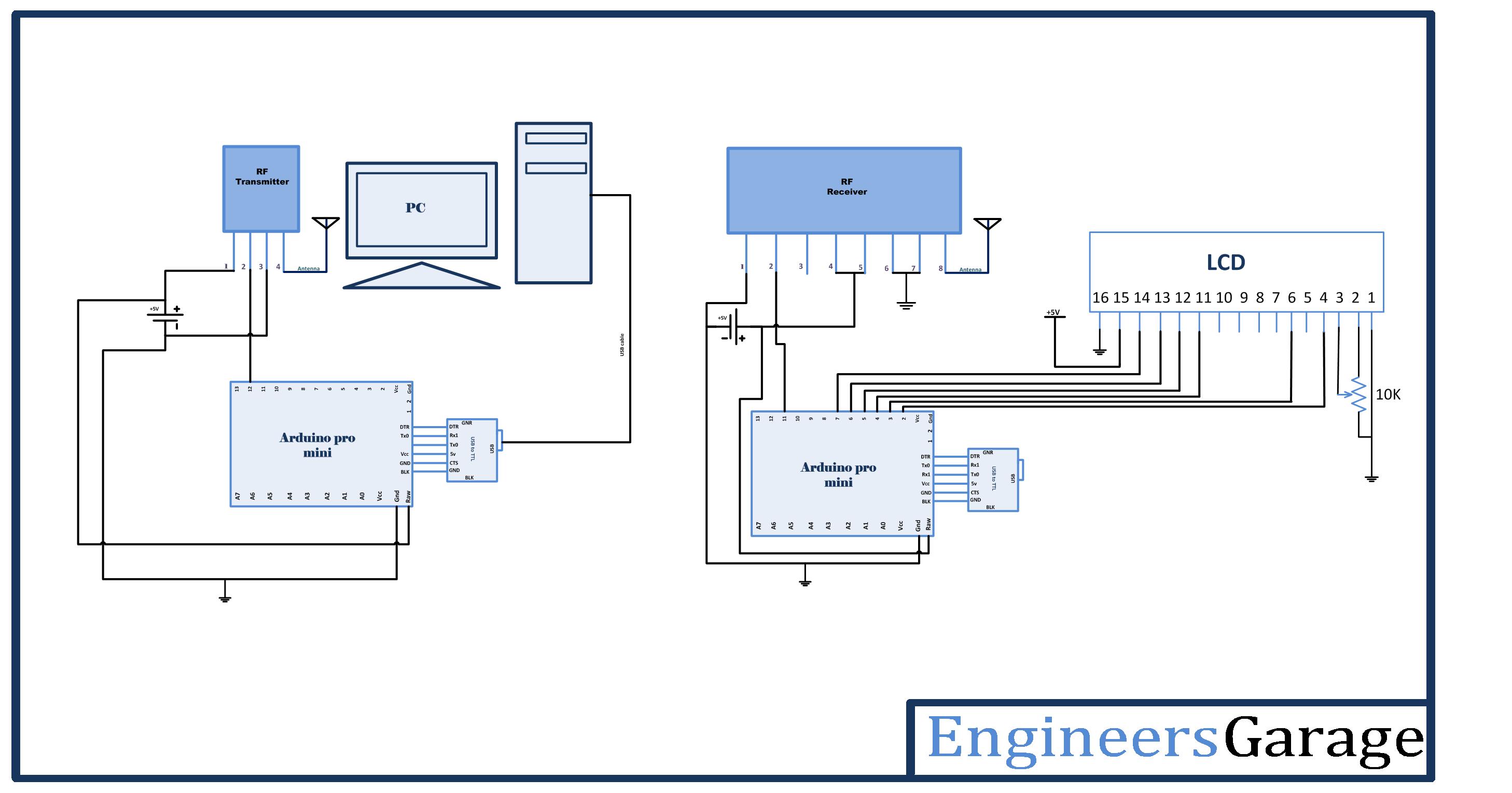
The data to be transmitted to the display units is passed using the serial monitor on the PC. For connecting the PC to RF, the first PC is connected to the Arduino board using the USB cable. The RF transmitter is directly interfaced to the Arduino by connecting its serial input pin (Pin 2) to Pin 12 of the Arduino Pro Mini and an antenna connected to pin 4 of the module. At the receiver display unit, an RF receiver is connected to another Arduino Pro Mini with serial out pin (Pin 2) connected to pin 11 of the receiver side Arduino board and an antenna connected to pin 8 of the RF module. An LCD is interfaced to the receiver side Arduino board for displaying transmitted messages. The 16X2 LCD display is connected to the Arduino board by connecting its data pins to pins 7 to 4 of the Arduino board. The RS and E pins of LCD are connected to pins 3 and 2 of the Arduino Pro Mini respectively. The RW pin of the LCD is grounded.
| LCD | Arduino UNO |
|---|---|
| RS | 3 |
| RW | GRND |
| E | 2 |
| D7,D6,D5,D4 | 7,6,5,4 Respectively |
The standard code library for interfacing Arduino UNO and Arduino Pro Mini are used in the project to program LCD with the board.
How the Circuit Works
The characters that have to be transmitted are passed from the serial monitor of PC. These characters are read by the Arduino board using the USB connection. The character read by the microcontroller remains in the buffer. The VirtualWire library is used in the program code to transmit the characters in the buffer through the RF. Since the library allows only to transmit one character serially at a time. The characters in the buffer first need to be stored in an array and each element of the array has to be serially out one by one.
At the receiver side, the character buffer is detected by the RF receiver and serially passed to the receiver side Arduino Pro Mini. The receiver side Arduino Pro Mini has the embedded program code to fetch the character buffer to an array and convert each character element to a respective integer representation. The integer representation of the characters is passed to 16X2 LCD for message display.

Fig. 3: Prototype of Arduino Circuit for RF data communication with PC
Programming Guide
At the transmitter side Arduino, first, the VirtualWire library is imported to facilitate interfacing with RF module.
#include <VirtualWire.h>
A LED is connected at pin 13 to indicate serial transmission in progress. So, a variable “ledpin” is declared and assigned to pin 13 of the Arduino. The “MsgData” variable is declared to store the character reading and “MsgcharAR” array is declared to hold multiple characters before serial transmission. Some global variables – “length” to store the length of the message, “data_available” to check data availability and a counter “i” are initialized.
A setup() function is called, where, ledpin is set to output mode using the pinMode() function, the baud rate of the system is set to 9600 bits per second using the Serial.begin() function and vw_setup() function is used to set the baud rate of RF serial transmission to 2000 bits per second.
A loop() function is called, inside which, first length variable is initialized to 0 and serial data is checked if available using the Serial.available() function. If serial data is available, it is read using Serial.read() function and stored to MsgcharAR array. The length counter is incremented and data_available is set to 1 for Boolean logic. The code block is repeated in a While() loop until serial data is available.
If data is available, dat_available flag variable is left to a Boolean setting of 1, then the message stored in MsgcharAR array is serially out to buffer using the Serial.print() function.
The message stored in the buffer has to be serially out on RF. The led indicating transmission in progress is switched ON by sending a HIGH logic to ledpin. The message is sent out serially on RF using the vw_send() function, where, message characters are first converted to unsigned character form. vw_wait_tx() is used to wait till the entire message is transmitted out. When the transmission is over, the ledpin is sent a LOW logic to switch the transmission in progress LED OFF.
The data_available is set to 0 and each element of MsgcharAR array is set to 0 as the default value.
data_available = 0;
This ends the transmitter side Arduino Code
On the receiver side Arduino, the program code first imports the required standard libraries. LiquidCrystal.h is imported to interface the LCD and VirtualWire library is imported to read serial input from the RF receiver. The pins 2 to 7 are mapped to Liquid Crystal object LCD.
The pin 13 where transmission progress indicator LED is connected is assigned to ledpin variable and two variables – “Sensor1Data” to capture the message in integer form and “Sensor1CharMsg” to store character representation of the message to be displayed are declared.
A setup() function is called where baud rate of the Arduino is set to 9600 bits per second using Serial.begin() function. The LCD object is initialized to a 16X2 mode and initial messages are flashed to the LCD. The led connected pin and pin connected to RS and RW are set to output mode using the pinMode() function.
The RF transmitter and receiver module does not have Push To Talk pin. They go inactive when no data is present to transmit or receive respectively. Therefore vw_set_ptt_inverted(true) is used to configure push to talk polarity and prompt the receiver to continue receiving data after fetching the first character. The baud rate for serial input is set to 2000 bits per second using the vw_setup() function. The reception of the data is initiated using vw_rx_start().
A loop() function is called inside which, array “buf[]” to read serial buffer and “buflen” variable to store buffer length are declared.
The character buffer is detected using the vw_get_message() function, if it is present, a counter “i” is initialized and LED connected to pin 13 is switched on by sending a HIGH at pin 13 to indicate successful detection of the character buffer.
The character buffer is stored in the Sensor1CharMsg array using the for loop with the initialized counter.
The null character is detected in the buffer stream so that no garbage value goes to the LCD display. The characters received from the buffer are converted to the integer value and stored in “Sensor1Data” variable.
The variable value along with relevant strings enclosed is passed to the microcontroller’s buffer and passed to the LCD for display in a presentable format.
This ends the loop() function and the receiver side Arduino code.
You may also like:


Project Source Code
###
#include// LED's const int ledPin = 13; int MsgData; //int Sensor2Data; char MsgcharAR[40]; int length,data_available; int i; void setup() { // PinModes // LED pinMode(ledPin,OUTPUT); // for debugging Serial.begin(9600); // VirtualWire setup vw_setup(2000); // Bits per sec }void setup() { // PinModes // LED pinMode(ledPin,OUTPUT); // for debugging Serial.begin(9600); // VirtualWire setup vw_setup(2000); // Bits per sec }MsgcharAR[length] = Serial.read(); length++; delay(100); data_available = 1; }// Convert integer data to Char array directly // itoa(data,Sensor1CharMsg,10); if(data_available == 1) { // DEBUG Serial.print(" Sending data : "); Serial.println(MsgcharAR); //Serial.println(" "); delay(1000); // END DEBUGdigitalWrite(13, true); // Turn on a light to show transmitting vw_send((uint8_t *) MsgcharAR, length); vw_wait_tx(); // Wait until the whole message is gone digitalWrite(13, false); // Turn off a light after transmission delay(200); for(i = 0 ; i < 40 ; i++) { MsgcharAR [i] = 0; }} } // END void loop... #include#include LiquidCrystal lcd(2, 3, 4, 5, 6, 7); // LED's int ledPin = 13; // Sensors int Sensor1Data; // RF Transmission container char Sensor1CharMsg[4]; void setup() { Serial.begin(9600); lcd.begin(16, 2); lcd.print("ENGINEERS GARAGE"); lcd.setCursor(0, 1); // sets the digital pin as output pinMode(ledPin, OUTPUT); pinMode(9, OUTPUT); pinMode(8, OUTPUT);// VirtualWire // Initialise the IO and ISR // Required for DR3100 vw_set_ptt_inverted(true); // Bits per sec vw_setup(2000); // Start the receiver PLL running vw_rx_start(); } // END void setupvoid loop(){ uint8_t buf[VW_MAX_MESSAGE_LEN]; uint8_t buflen = VW_MAX_MESSAGE_LEN; // Non-blocking if (vw_get_message(buf, &buflen)) {int i; // Turn on a light to show received good message digitalWrite(13, true); // Message with a good checksum received, dump it. for (i = 0; i < buflen; i++){ // Fill Sensor1CharMsg Char array with corresponding // chars from buffer. Sensor1CharMsg[i] = char(buf[i]); }// Null terminate the char array // This needs to be done otherwise problems will occur // when the incoming messages has less digits than the // one before. Sensor1CharMsg[buflen] = ''; // Convert Sensor1CharMsg Char array to integer Sensor1Data = atoi(Sensor1CharMsg);// DEBUG Serial.print("Sensor 1: "); Serial.println(Sensor1Data); lcd.setCursor(0, 2); lcd.print("Temperature ="); lcd.print(Sensor1Data); // change the analog out value: if(Sensor1Data > 50){ digitalWrite(9,HIGH); delay(2000); }digitalWrite(9,LOW); } }###
Circuit Diagrams
Project Video
Filed Under: Tutorials
Filed Under: Tutorials

Questions related to this article?
👉Ask and discuss on EDAboard.com and Electro-Tech-Online.com forums.
Tell Us What You Think!!
You must be logged in to post a comment.