Humidity and temperature monitoring systems are quite common in industries. These environment factors need constant supervision to maintain reliability and efficiency of the industrial devices. The monitoring systems used in industries are generally wired where sensor unit and the sensor monitoring system connects through a cable wire. The humidity and temperature monitoring systems can be made wireless using the 434 RF modules. With wireless connectivity, the sensor and the monitoring systems can be installed separately and industrial equipment can be remotely supervised. Plus, the cost for extensive cable installation is also saved.
The 434 RF modules have an operational range of 50-60 metre and can be extended to 300-350 metre using an antenna and increasing the transmission power. Therefore, RF modules attached to the antenna can be easily installed anywhere and can perform wireless data communication with an impressive range. (Even a Wi-Fi router have range limited to 45 metre indoor and 92 metre outdoor).
This project uses a DHT11 humidity and temperature sensor and is built on Arduino Pro Mini. The RF modules are directly interfaced to Arduino boards for wireless implementation. The sensor readings are displayed on a 16X2 LCD screen.
Components Required
| Sr. No. | Components Required | Quantity |
|---|---|---|
| 1. | RF Rx module(434Mhz) | 1 |
| 2 | RF Tx Module (434Mhz) | 1 |
| 3 | Arduino pro mini | 2 |
| 4 | DHT11 | 1 |
| 5 | LCD | 1 |
| 6 | Battery – 9V | 2 |
| 7 | Breadboard | 2 |
| 8 | Connecting wires |

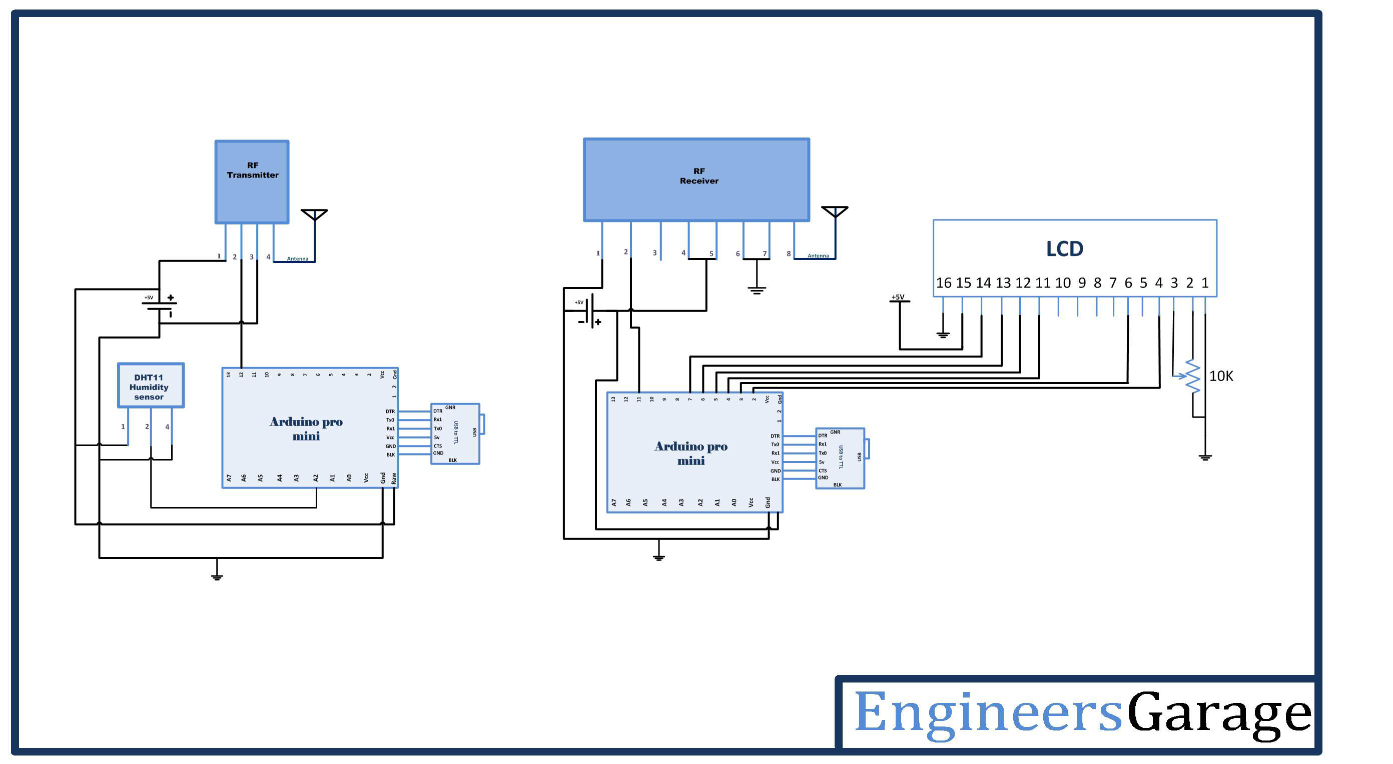
Fig. 1: Block Diagram of Arduino based Wireless Humidity and Temperature Monitor
Circuit Connections
There are two circuits in the project – a) Temperature and humidity sensor circuit and b) Sensor reading display circuit. In the sensor circuit, the data pin (Pin 2) of DHT11 sensor is connected to A2 analog pin of the Arduino Pro Mini. The pins VCC (Pin 1) and Ground (Pin 4) are connected to VCC and ground respectively. An RF transmitter is interfaced to the Arduino board with its serial input pin (Pin 2) connected to pin 12 of the Arduino board. An antenna is connected to pin 4 of the transmitter for range extension.
On the display circuit, an RF receiver is connected to another Arduino Pro Mini with serial out pin (Pin 2) of the receiver connected to pin 11 of Arduino. An antenna is connected to pin 8 of the receiver for range extension. An LCD is interfaced to the Arduino board for displaying temperature and humidity readings. The 16X2 LCD display is connected to the Arduino board by connecting its data pins to pins 7 to 4 of the Arduino board. The RS and E pins of LCD are connected to pins 3 and 2 of the Arduino Pro Mini respectively. The RW pin of the LCD is grounded.

Fig. 2: Table listing circuit connections between Character LCd and Arduino Uno
The standard code library for interfacing Arduino UNO and Arduino Pro Mini are used in the project to program LCD with the board.
How the Circuit Works
DHT11 Temperature and Humidity Sensor is a digital sensor with inbuilt capacitive humidity sensor and Thermistor. It relays a real-time temperature and humidity reading every 2 seconds. The sensor operates on 3.5 to 5.5 V supply and can read temperature reading between 0° C and 50° C and relative humidity between 20% and 95%.
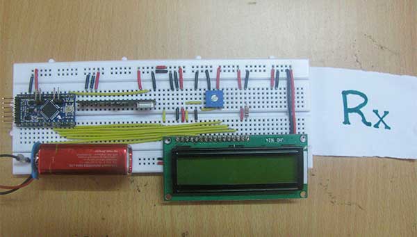
Fig. 3: Prototype of Wireless Humidity and Temperature Monitor
The sensor cannot be directly interfaced to a digital pin of the board as it operates on 1-wire protocol which must be implemented in the firmware. First, the data pin is configured to input and a start signal is sent to it. The start signal comprises of a LOW for 18 milliseconds followed by a HIGH for 20 to 40 microseconds followed by a LOW again for 80 microseconds and a HIGH for 80 microseconds.
After sending the start signal, the pin is configured to digital output and 40-bit data comprising of the temperature and humidity reading is latched out. Of the 5-byte data, the first two bytes are integer and decimal part of reading for relative humidity respectively, third and fourth bytes are integer and decimal part of reading for temperature and last one is checksum byte. When interfacing DHT11 with Arduino, already a code library is available and the sensor data can be read by read11() function of the DHT class.

Fig. 4: Image showing Arduino used in Wireless Humidity and Temperature Monitor
On the sensor circuit, the temperature and relative humidity readings are first fetched by the Arduino and their character representation are stored in separate arrays. The character buffer is serially transmitted on the RF using the VirtualWire library of the Arduino. Check out the transmitter side Arduino program code to learn how Arduino gets the sensor value and store them to arrays for RF transmission.
On the display circuit, character representation of sensor readings is detected by the RF receiver and serially passed to receiver side Arduino board. The program code on receiver side Arduino board reads the character buffer and convert it to integer form for displaying on LCD. The standard functions of the lcd library are used to display readings on LCD. Check out the receiver side Arduino code to learn how sensor values are read from the buffer and converted to a proper format for display on the LCD screen.
Programming Guide
On the transmitter side Arduino, first, the program code imports the required standard libraries. The VirtualWire library is required to connect with RF module and DHT library is needed to interface DHT11 sensor. A “DHT” object is instantiated. Global variables ledPin and Sensor1Pin are declared and mapped to Pin 13 where transmission progress indicator LED is connected and Pin A2 where data pin of DHT11 temperature and humidity sensor is connected respectively. A variable Sensor1Data is declared to stored sensor reading and character type arrays Sensor1CharMsg and Sensor1CharMsg1 are declared to store a decimal representation of the relative humidity and temperature reading.
A setup() function is called where indicator LED pin is set to output while sensor connected pin is set to input mode using pinMode() function. The baud rate of the Arduino is set to 9600 bits per second using the serial.begin() function. The initial messages are flashed to the buffer using Serial.Println() function. The baud rate for serial output is set to 2000 bits per second using the vw_setup() function of the VirtualWire library.
A loop function is called where reading from DHT11 sensor are read using the read11() function on DHT object and the character representation of decimal base of the humidity reading is stored in Sensor1CharMsg array and the character representation of decimal base of the temperature reading is stored in Sensor1CharMsg1 array.
The sensor readings are serially out as human-readable ASCII text using the Serial.print() and Serial.println() function.
The transmission progress indicator LED is switched on by passing a HIGH to pin 13. The character message containing the temperature and humidity reading is sent serially using the vw_send() function and vw_wait_tx() is used to block transmission until a new message is available for transmission. The LED at pin 13 is switched OFF by passing a LOW to indicate successful transmission of the message.
This ends the transmitter side Arduino code.
On the receiver side Arduino, the program code first imports the required standard libraries. LiquidCrystal.h is imported to interface the LCD and VirtualWire library is imported to read serial input from the RF receiver. The pins 2 to 7 are mapped to Liquid Crystal object LCD.
The pin 13 where transmission progress indicator LED is connected is assigned to ledpin variable and two variables – “Sensor1Data” and “Sensor2Data” to capture reading of DHT11 in integer form and arrays “Sensor1CharMsg1” and “Sensor1CharMsg2” to store character representation of the readings are declared. There are counter variables “i” and “j” also declared.
A setup() function is called where baud rate of the Arduino is set to 9600 bits per second using Serial.begin() function. The LCD object is initialized to 16X2 mode. The led connected pin and pin connected to RS and RW are set to output mode using the pinMode() function.
A loop() function is called inside which, array “buf[]” to read serial buffer and “buflen” variable to store buffer length are declared. The counter variables are initialized to zero.
The character buffer is detected using the vw_get_message() function if it is present, a counter “i” is initialized. The buffer readings are first stored to RxAray array using the for loop with the initialized counter and after detecting the null character, the temperature and humidity sensor readings clubbed in RxAray are separately stored to “SensorCharMsg1″ and ” SensorCharMsg2″ arrays.
The variable value along with relevant strings enclosed is passed to the microcontroller’s buffer and passed to the LCD for display in a presentable format.
This ends the loop() function and the receiver side Arduino code.
You may also like:


Project Source Code
###
#include#include #define dht_dpin A0 //no ; here. Set equal to channel sensor is on dht DHT; // LED's const int ledPin = 13; // Sensors const int Sensor1Pin = A2; int Sensor1Data; char Sensor1CharMsg[4]; char Sensor1CharMsg1[4]; void setup() { // PinModes // LED pinMode(ledPin,OUTPUT); // Sensor(s) pinMode(Sensor1Pin,INPUT); Serial.begin(9600); delay(300);//Let system settle Serial.println("Humidity and temperaturenn"); delay(700); // VirtualWire setup vw_setup(2000); // Bits per sec } void loop() { // Read and store Sensor 1 data // Sensor1Data = analogRead(Sensor1Pin); DHT.read11(dht_dpin); // Convert integer data to Char array directly itoa(DHT.humidity,Sensor1CharMsg,10); itoa(DHT.temperature,Sensor1CharMsg1,10); The sensor readings are serially out as human-readable ASCII text using the Serial.print() and Serial.println() function. // DEBUG Serial.print("Current humidity = "); Serial.print(DHT.humidity); Serial.print("% "); Serial.print("temperature = "); Serial.print(DHT.temperature); Serial.println("C "); delay(800); // END DEBUG digitalWrite(13, true); // Turn on a light to show transmitting vw_send((uint8_t *)Sensor1CharMsg, strlen(Sensor1CharMsg)); vw_wait_tx(); // Wait until the whole message is gone delay(200); vw_send((uint8_t *)Sensor1CharMsg1, strlen(Sensor1CharMsg1)); vw_wait_tx(); // Wait until the whole message is gone digitalWrite(13, false); // Turn off a light after transmission delay(200); } // END void loop... #include #include LiquidCrystal lcd(2, 3, 4, 5, 6, 7); // LED's int ledPin = 13; // Sensors int Sensor1Data; int Sensor2Data; // RF Transmission container char SensorCharMsg1[4]; char rxAray[8]; char SensorCharMsg2[4]; int j,k; void setup() { Serial.begin(9600); lcd.begin(16, 2); // sets the digital pin as output pinMode(ledPin, OUTPUT); pinMode(9, OUTPUT); pinMode(8, OUTPUT); // VirtualWire // Initialise the IO and ISR // Required for DR3100 vw_set_ptt_inverted(true); // Bits per sec vw_setup(2000); // Start the receiver PLL running vw_rx_start(); } // END void setup void loop(){ uint8_t buf[VW_MAX_MESSAGE_LEN]; uint8_t buflen = VW_MAX_MESSAGE_LEN; j = 0; k = 0; // Non-blocking if (vw_get_message(buf, &buflen)) { int i; // Message with a good checksum received, dump it. for (i = 0; i < buflen; i++) { // Fill Sensor1CharMsg Char array with corresponding // chars from buffer. rxAray[i] = char(buf[i]); } rxAray[buflen] = ''; while( j < 2) { SensorCharMsg1[j++] = rxAray[j++]; } while( j < 4) { SensorCharMsg2[k++] = rxAray[j++]; } // DEBUG Serial.print(" hum = "); Serial.println(SensorCharMsg1); Serial.print(" temp = "); Serial.println(SensorCharMsg2); lcd.setCursor(0,0); lcd.print("Humidity = "); lcd.print(SensorCharMsg1); // change the analog out value: lcd.setCursor(0,1 ); lcd.print("Temparature = "); lcd.print(SensorCharMsg2); // END DEBUG } }
###
Circuit Diagrams
Project Video
Filed Under: Tutorials
Filed Under: Tutorials

Questions related to this article?
👉Ask and discuss on Electro-Tech-Online.com and EDAboard.com forums.
Tell Us What You Think!!
You must be logged in to post a comment.