Due to wired connection between the robot and the remote controller, its range of motion gets restricted or requires a human to follow along the robot. Such restriction for a “Moving Metal” is obviously the biggest drawback. So why not replace the wired connectivity with a wireless one.
This project is a demonstration of similar wireless remote controlling applicable to two-wheel drive robots. The wireless remote is a 434 RF module and the robot is driven on DC motors controlled by an L293D motor driver IC. Typically, 434 RF modules have a range of 50-60 metre but can be extended up to 300-350 metre. So, after extending the operational range of RF module, the RC robot will have an impressive distance to wander around. Learn more about extending the operational range of RF modules by attaching an antenna of standard size and increasing the transmission power.
In the project, intelligence to interpret control signal from the remote controller and to follow up a consequent action comes through Arduino Pro Mini. The robot built up in the project can move forward, backward, turn right, turn left and can be stopped. This requires a set of 5 control signals over 4-bit data of 434 RF module and need only single bit of the 4-bit signal to set high at a time. The stopped condition of the robot is default condition and none of the control bits set high can stimulate the default stop condition. The remote controller is built on a breadboard and control signal has been provided through tactile switches.
Components Required
| Sr. No. | Components Required | Quantity |
|---|---|---|
| 1 | RF Tx Module (434 Mhz) | 1 |
| 2 | RF Rx Module (434 Mhz) | 1 |
| 3 | HT12E | 1 |
| 4 | HT12D | 1 |
| 5 | LED | 1 |
| 6 | Resistor – 1KΩ (Quarter watt) | 12 |
| 7 | Resistor – 1MΩ (Quarter watt) | 1 |
| 8 | Resistor – 50KΩ (Quarter watt) | 1 |
| 9 | Pushbutton | 4 |
| 10 | DC Motor | 4 |
| 11 | Battery – 9V | 1 |
| 12 | Battery – 12V | 1 |
| 13 | L293D | 2 |
| 14 | Opto – coupler (MCT12E827Q) | 8 |
| 15 | Breadboard | 3 |
| 16 | Arduino development board | 1 |
| 17 | Connecting wires |

BLOCK DIAGRAM
Circuit Connections
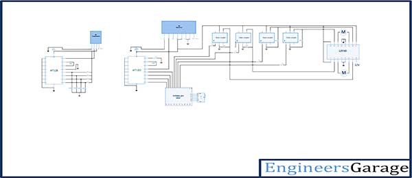
The project has two circuits. One circuit is the remote controller and other is the robot circuit. The remote controller is a simple RF transmitter having the basic setup and configuration. So the remote has an RF transmitter connected to HT12E encoder IC to its pin 2 and an antenna connected to its pin 4. The address bits of the HT12E are hard-wired to ground to assign it an address byte of 0x00. The pin 14 of the transmitter is also hard-wired to ground to enable continuous transmission of control signal. The data pins of the HT12E are connected to ground by default but have access to VCC through tactile switches. The tactile switches are connected to data pins of HT12E in following configuration and alter the control signal as mentioned in the table below.
| Switch | Connected to Data Pin |
Control Signal Passed On Pressing Switch |
|---|---|---|
| Move Forward | D0 | 0x1 |
| Move Backward | D1 | 0x2 |
| Turn Right | D2 | 0x4 |
| Turn Left | D3 | 0x8 |
Tactile Switch Connections
When the robot has to be stopped no switch should be pressed as the default status of the robot is a stopped condition
The robot is made on a metallic frame and four wheels have been connected to it. Though the robot has a two wheel drive and DC motors are attached to only two wheels of the robot. The DC motor is controlled by an L293D IC which can control two DC motors effectively. The L293D’s input pins are connected to Arduino’s digital input/output pins 9 down to 6 through opto-couplers while 4-bit control signal from the RF remote is fetched by an RF receiver which pass the signal to HT12D decoder whose data out pins are connected to pins 13 down to 10 of the Arduino board. The HT12D decoder has all its address bits connected to ground to match the transmitter address 0x00 and receives serial 4-bit data from the RF receiver having an antenna extension. Learn more about interfacing and controlling DC motors by RF module.
How the Circuit Works
The remote controller circuit is an RF transmitter having an address byte of 0x00 and configured to uninterrupted transmission by connecting pin 14 to default LOW. The data pins of the HT12E IC are by default grounded hence the default signal transmitted over the system is 0x0. The tactile switches connected to the data pins via VCC provides the control signals to maneuver the robot. Pressing the tactile switches transmits the control signals as mentioned in Tactile Switch Connections table.
At the robot circuit, the transmitted signals are fetched by the antenna and passed serially to the HT12D IC through the RF receiver. The same 4-bit control signal is reflected at the data bits of HT12D IC. The data bits D0 to D3of HT12E are connected to pin 13 down to 10 of the Arduino board. The program code initialize these pins as digital input and run program logic according to the received signal. The signal remains on pins and to on reception until a new signal is received because of the latch-type nature of both the HT12D and Arduino I/O pins.
The program code outputs motor control signals according to the signal received by the remote control. The motor control signals are processed by an L293D IC which follows the following truth tables :
| Pin 1/Enable Inputs 1 and 2 | Pin 2/Input 1 | Pin 7/Input 2 | Motor Connected between Pins 3 and 6)Function |
|---|---|---|---|
| LOW | N/A | N/A | Motor Stops |
| HIGH | HIGH | HIGH | Motor Stops |
| HIGH | LOW | LOW | Motor Stops |
| HIGH | HIGH | LOW | Motor Turns Anti-Clockwise |
| HIGH | LOW | HIGH | Motor Turns Clockwise |
| Pin 9/Enable Inputs 3 and 4 | Pin 10/Input 3 | Pin 15/Input 4 | Motor Connected between Pins 11 and 14) Function |
|---|---|---|---|
| LOW | N/A | N/A | Motor Stops |
| HIGH | HIGH | HIGH | Motor Stops |
| HIGH | LOW | LOW | Motor Stops |
| HIGH | HIGH | LOW | Motor Turns Anti-Clockwise |
| HIGH | LOW | HIGH | Motor Turns Clockwise |
In the robot, circuit considering the two-wheel drive either front or rear possible drive, right hand side (RHS) motor is connected between pins 3 and 6 and left hand side (LHS) motor is connected between pin 11 and 14 of the L293D. The RHS motor is controlled by pin 2 and 7 of the L293D while LHS motor is controlled by pin 10 and 15 of L293D. Hence, to move the robot in different directions following digital outputs are required at the L293D pins.
| Action | RHS Motor | LHS Motor | RHS Motor | LHS Motor | ||
| Pin 2 | Pin 7 | Pin 10 | Pin 15 | |||
| Move Forward | Clockwise Rotation | Anti-clockwise Rotation | LOW | HIGH | HIGH | LOW |
| Move Backward | Anti-clockwise Rotation | Clockwise Rotation | HIGH | LOW | LOW | HIGH |
| Turn Right | Stop | Anti-clockwise Rotation | LOW | LOW | HIGH | LOW |
| Turn Left | Clockwise Rotation | Stop | LOW | HIGH | LOW | LOW |
To turn the robot right, RHS motor has to be stopped and LHS motor needs to be rotated anti-clockwise. This is done by passing LOW signals to pin 2, 7 and 15 of L293D and HIGH signal to pin 10 of L293D according to the truth table. By a different logic (but not used in this project) to turn robot right in two-wheel drive model, RHS motor can be rotated anti-clockwise along with the LHS motor to reduce “Turning Radius”. However, the logic of rotating both motors for turning is more suitable for 3-wheel robots having a triangular body frame as a 4-wheel robot maygets unstable and toppled if the rectangular body frame does not have a suitably lower centre of gravity.So to drive robot forward in this two-wheel drive, RHS motor needs to be rotated clockwise and LHS motor needs to be rotated anticlockwise. This is done by passing LOW signals to pin 2 and 15 of L293D and HIGH signal to pin 7 and 10 of L293D according to the truth table. To drive robot backward (applicable to two wheel drive) RHS motor needs to be rotated anti-clockwise and LHS motor needs to be rotated clockwise. This is done by passing LOW signals to pin 7 and 10 of L293D and HIGH signal to pin 2 and 15 of L293D according to the truth table.
To turn the robot left, LHS motor has to be stopped and RHS motor needs to be rotated in clockwise direction. This is done by passing LOW signals to pin 2, 10 and 15 of L293D and HIGH signal to pin 7 of L293D according to the truth table. Again if logic of rotating both motors to turn the robot (provided robot is a 3-wheel triangular body frame vehicle or has rectangular body with lower centre of gravity) is used, both motors shall need to be rotated clock-wise. The motors are stopped in the project by giving both control inputs of L293D for each motor a LOW logic.
The L293D pins are connected to Arduino pins in following manner and accordingly for robot’s motion they need to be passed the mentioned digital output.
| L293D Pin | Arduino Pin | Move Forward | Move Backward | Turn Right | Turn Left |
|---|---|---|---|---|---|
| 2 | 8 | LOW | HIGH | LOW | LOW |
| 7 | 9 | HIGH | LOW | LOW | HIGH |
| 10 | 7 | HIGH | LOW | HIGH | LOW |
| 15 | 6 | LOW | HIGH | LOW | LOW |
The Arduino pins 9 down to 6 are initialized to digital output in the program code and assigned respective statuses as mentioned in the above table for moving the robot.
This is as that simple, the RF remote control passes the control signal which can be changed by pressing the tactile switches interfaced directly to the HT12E data pins. In the robot circuit, control signals are received and passed to Arduino board by the RF receiver. These signals are read by the program code and relevant digital outputs are latched out to the pins connecting with L293D IC’s motor control pins. The digital outputs that need to be passed through Arduino board depends on the hard-wired interfacing of L293D pins with the Arduino digital out pins and the configuration of the DC motors around L293D IC.
Programming Guide
First the Arduino pins are assigned variables so that they can be referenced in the code. In a setup() function, the pins 10 to 13 are configured digital input to receive nibble from the RF section and pins 6 to 9 are configured digital output for proving motor control signals. The digital I/O mode is set by the pinMode() function. The baud rate is set to 9600 bits per second using the Serial.begin() function inside the setup() function.
The control signal at pins 13 to 10 are read using digitalRead() function and assigned to variables inside a loop() function. The default robot status of stopped robot is executed by stopping both motors for which LOW signal is passed to all the output pins. The control signal bits are checked through an if-else-if logic.
The 0x1 signal corresponding to move robot forward is checked by comparing Tx1 variable status to HIGH and the respective output as mentioned in Digital Out Logic table is passed using the digitalWrite() function.
The 0x2 signal corresponding to move robot backward is checked by comparing Tx2 variable status to HIGH and the respective output as mentioned in Digital Out Logic table is passed using the digitalWrite() function.
The 0x4 signal corresponding to turn robot right is checked by comparing Tx3 variable status to HIGH and the respective output as mentioned in Digital Out Logic table is passed using the digitalWrite() function.
The 0x8 signal corresponding to turn robot left is checked by comparing Tx4 variable status to HIGH and the respective output as mentioned in Digital Out Logic table is passed using the digitalWrite() function.
Project Source Code
Project Source Code
###
//decoder 10,11,12,13 output pins connected to Arduino 10,11,12,13 digital pins as input. int tx1 = 10; int tx2 = 11; int tx3 = 12; int tx4 = 13; //decoder 10,11,12,13 output pins connected to Arduino 6,7,8,9 digital pins as input. int m11 = 8; int m12 = 9; int m21 = 7; int m22 = 6; void setup(){ pinMode(tx1,INPUT); pinMode(tx2,INPUT); pinMode(tx3,INPUT); // decoder output microcontroller reading as input. pinMode(tx4,INPUT); pinMode(m11,OUTPUT); pinMode(m12,OUTPUT); pinMode(m21,OUTPUT); // led's as output. pinMode(m22,OUTPUT); Serial.begin(9600); } void loop(){ // reading data and storing in a variable for further use. int Tx1 = digitalRead(tx1); int Tx2 = digitalRead(tx2); int Tx3 = digitalRead(tx3); int Tx4 = digitalRead(tx4); digitalWrite(m11,LOW); digitalWrite(m12,LOW); digitalWrite(m21,LOW); digitalWrite(m22,LOW); if (Tx1 == HIGH ){ digitalWrite(m11,LOW); digitalWrite(m12,HIGH); digitalWrite(m21,HIGH); digitalWrite(m22,LOW); } else if (Tx2 == HIGH){ digitalWrite(m11,HIGH); digitalWrite(m12,LOW); digitalWrite(m21,LOW); digitalWrite(m22,HIGH); } else if (Tx3 == HIGH){ digitalWrite(m11,LOW); digitalWrite(m12,LOW); digitalWrite(m21,HIGH); digitalWrite(m22,LOW); } else if (Tx4 == HIGH ){ digitalWrite(m11,LOW); digitalWrite(m12,HIGH); digitalWrite(m21,LOW); digitalWrite(m22,LOW); } }###
Circuit Diagrams
Project Video
Filed Under: Featured Contributions
Filed Under: Featured Contributions
Log in to leave a comment:
Lost your password?
Don't have an account? Register here