Engineers Garage

  • Electronic Projects & Tutorials
    • Electronic Projects
      • Arduino Projects
      • AVR
      • Raspberry pi
      • ESP8266
      • BeagleBone
      • 8051 Microcontroller
      • ARM
      • PIC Microcontroller
      • STM32
    • Tutorials
      • Audio Electronics
      • Battery Management
      • Brainwave
      • Electric Vehicles
      • EMI/EMC/RFI
      • Hardware Filters
      • IoT tutorials
      • Power Tutorials
      • Python
      • Sensors
      • USB
      • VHDL
    • Circuit Design
    • Project Videos
    • Components
  • Articles
    • Tech Articles
    • Insight
    • Invention Stories
    • How to
    • What Is
  • News
    • Electronic Product News
    • Business News
    • Company/Start-up News
    • DIY Reviews
    • Guest Post
  • Forums
    • EDABoard.com
    • Electro-Tech-Online
    • EG Forum Archive
  • DigiKey Store
    • Cables, Wires
    • Connectors, Interconnect
    • Discrete
    • Electromechanical
    • Embedded Computers
    • Enclosures, Hardware, Office
    • Integrated Circuits (ICs)
    • Isolators
    • LED/Optoelectronics
    • Passive
    • Power, Circuit Protection
    • Programmers
    • RF, Wireless
    • Semiconductors
    • Sensors, Transducers
    • Test Products
    • Tools
  • Learn
    • eBooks/Tech Tips
    • Design Guides
    • Learning Center
    • Tech Toolboxes
    • Webinars & Digital Events
  • Resources
    • Digital Issues
    • EE Training Days
    • LEAP Awards
    • Podcasts
    • Webinars / Digital Events
    • White Papers
    • Engineering Diversity & Inclusion
    • DesignFast
  • Guest Post Guidelines
  • Advertise
  • Subscribe

NxN(8×1 , 8×2 , 10×2 , 16×1 , 16×2 , 16×4 , 20×2 , 20×4 ,24×2 , 30×2 , 32×2 , 40×2) Character lcd working, Pinout and description

By EG Projects September 17, 2019

Lcd stands for liquid crystal display. Character and graphical lcd’s are most common among hobbyist and diy electronic circuit/project makers. Since their interface serial/parallel pins are defined so its easy to interface them with many microcontrollers. Many products we see in our daily life have lcd’s with them. They are used to show status of the product or provide interface for inputting or selecting some process. Washing machine, microwave,air conditioners and mat cleaners are few examples of products that have character or graphical lcd’s installed in them. In this tutorial i am going to discuss about the character lcd’s. How they work? their pin out and initialization commands etc.

Lcd sizes

​Character lcd’s come in many sizes 8×1, 8×2, 10×2, 16×1, 16×2, 16×4, 20×2, 20×4, 24×2, 30×2, 32×2, 40×2 etc . Many multinational companies like Philips, Hitachi, Panasonic make their own custom type of character lcd’s to be used in their products. All character lcd’s performs the same functions(display characters numbers special characters, ascii characters etc).Their programming is also same and they all have same 14 pins (0-13) or 16 pins (0 to 15). ​
In an mxn lcd. M denotes number of columns and n represents number of rows. Like if the lcd is denoted by 16×2 it means it has 16 columns and 2 rows. Few examples are given below. 16×2, 8×1 and 8×2 lcd are shown in the picture below. Note the difference in the rows and columns.

16x2 Character Lcd Rows and Coulombs

16×2 Character Lcd Rows and Colulmns

8x1 Character Lcd Rows and Coulombs

8×1 Character Lcd Rows and Columns

8x2 Character Lcd Rows and Coulombs

8×2 Character Lcd Rows and Columns

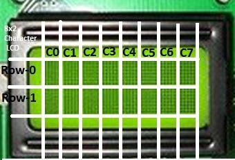
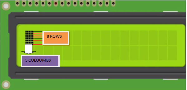
How character is made on lcd?

On a character lcd a character is generated in a matrix of 5×8 or 5×7. Where 5 represents number of columns and 7/8 represent number of rows. Maximum size of the matrix is 5×8. You can not display character greater then 5×8 dimension matrix. Normally we display a character in 5×7 matrix and left the 8th row for the cursor. If we use the 8th row of the matrix for the character display, then their will be no room for cursor. The picture below shows the 5×8 dot matrix pixels arrangement.

16x2 lcd single character rows and coulombs

16×2 lcd single character rows and columns
To display character greater than this dimension you have to switch to graphical lcd’s. To learn about graphical lcds here is a good tutorial Graphical Lcd’s Working and Pin out.

Lcd 16×2 Pin out

All character lcd’s have 

  • Eight(8) data pins D0-D7
  • Vcc (Apply +5 volt here)
  • Gnd (Ground this pin)
  • Rc (Register select)
  • Rw (read – write)
  • En (Enable)
  • V0 (Set Lcd contrast)

16×2 lcd pin out diagrammatically is shown below. 

16x2 lcd pinout

16×2 lcd pinout
The picture above shows the pin out of the character lcd. Almost all the character lcd’s are composed of the same pin out. Lcd’s with total pin count equal to 14 does not have back light control option. They might have back light always on or does not have a back light. 16 total pin count lcd’s have 2 extra A and K pins. A means anode and K cathode, use these pins to control the back light of lcd.

Character lcd controller – HD44780

Character Lcd’s have a controller build in to them named HD44780. We actually talk with this controller in order to display character on the lcd screen. HD44780 must be properly handled and initialized before sending any data to it. HD44780 has some registers which are initialized and  manipulated for character displaying on the lcd. These registers are selected by the pins of character lcd. 

Lcd Rs(Register select) Pin

Register select selects the HD44780 controller registers. It switches between Command and data register.                      

  • Command Register
  • Data Register

Command Register
When we send commands to lcd these commands go to Command register and are processed their. Commands with their full description are given in the picture below. When Rs=0 command register is selected.
Data Register
When we send Data to lcd it goes to data register and is processed their. When Rs=1 data register is selected.

Lcd RW(Read/Write) Pin

Rw pin is used to read and write data to HD44780 data and command registers. When Rw=1 we can read data from lcd. When Rw=0 we can write to lcd.

Lcd En(Enable) Pin

When we select the register Rs(Command and Data) and set Rw(read –  write) and placed the raw value on 8-data lines, now its time to execute the instruction. By instruction i mean the 8-bit data or 8-bit command present on Data lines of lcd. For sending the final data/command present on the data lines we use this enable pin. Usually it remains en=0 and when we want to execute the instruction we make it high en=1 for some mills seconds. After this we again make it ground en=0.

Lcd V0 of contrast set pin

To set lcd display sharpness use this pin. Best way is to use variable resistor such as potentiometer a variable current makes the character contrast sharp. Connect the output of the potentiometer to this pin. Rotate the potentiometer knob forward and backward to adjust the lcd contrast. 
NOTE: we can not send an integer, float, long, double type data to lcd because lcd is designed to display a character only. Only the characters that are supported by the HD44780 controller. See the HD44780 data sheet to find out what characters can we display on lcd.  The 8 data pins on lcd carries only  Ascii 8-bit code of the character to lcd. How ever we can convert our data in character type array and send one by one our data to lcd. Data can be sent using lcd in 8-bit or 4-bit mode. If 4-bit mode is used, two nibbles of data (First high four bits and then low four bits) are sent to complete a full eight-bit transfer. 8-bit mode is best used when speed is required in an application and at least ten I/O pins are available. 4-bit mode requires a minimum of seven bits. In 4-bit mode, only the top 4 data pins (4-7) are used. 

Standard Lcd Commands with their functions are described below.

nxn lcd initialization commands

nxn lcd initialization commands
Command 0x30 means we are setting 8-bit mode lcd having 1 line and we are initializing it to be 5×7 character display.Now this 5×7 is some thing which every one should know what it stands for. usually the characters are displayed on lcd in 5×8 matrices form. where 5 is total number of columns and is number of rows.Thus the above 0x30 command initializes the lcd to display character in 5 columns and 7 rows the last row we usually leave for our cursor to move or blink etc.

Lcd command meanings and functions

  • The command 0x38 means we are setting 8-bit mode lcd having two lines and character shape between 5×7 matrix.
  • The command 0x20 means we are setting 4-bit mode lcd having 1 line and character shape between 5×7 matrix.
  • The command 0x28 means we are setting 4-bit mode lcd having 2 lines and character shape between 5×7 matrix.
  • The command 0x06 is entry mode it tells the lcd that we are going to use.
  • The command 0x08 dispalys cursor off and display off but with out clearing DDRAM contents.
  • The command 0x0E displays cursor on and dispaly on.
  • The command 0x0c dispaly on cursor off(displays cursor off but the text will appear on lcd)
  • The command 0x0F dispaly on cursor blink(text will appear on screen and cursor will blink).
  • The command 0x18 shift entire dispaly left(shift whole off the text on the particular line to its left ).
  • The command 0x1C shift entire dispaly right(shift whole off the text on the particular line to its right).
  • The command 0x10 Moves cursor one step left or move cursor on step a head to left when ever new character is displayed  on the screen.
  • The command 0x14  Moves cursor one step right or move cursor on step a head to righ when ever new character is displayed on the screen. 
  • The command 0x01 clear all the contents of the DDRAM and also clear the lcd removes all the text from the screen.
  • The command 0x80 initialize the cursor to the first position means first line first matrix(start point) now if we add 1 in 0x80+1=0x81 the cursor moves to second matrix.

NOTE: You can send commands in hexadecimal or decimal form which one do you like the result is same because the microcontroller translate the command in 8-bit binary value and sends it to the lcd.

Difference between 4-bit and 8-bit Lcd Mode

Character Lcd’s can be used in 4-bit and 8-bit mode. Before you send commands and data to your lcd. Lcd must first be initialized. This initialization is very important for lcd that are made by Hitachi because they use HD44780 driver chip sets. Hd44780 Chip set  first has to be initialized before using it. If you don’t initialize it properly you will see nothing on your lcd.
​
For 8-bit mode, this is done as follows:

1. Wait more than 15 mill secs after power is applied.
2. Write command 0x30 to LCD and wait 5 milli seconds for the instruction to complete.
3. Write command 0x30 to LCD and wait 160 micro seconds for instruction to complete.
4. Write command 0x30 AGAIN to LCD and wait 160 micro seconds or Poll the Busy Flag.

In 4-bit mode the high nibble is sent first before the low nibble and the En pin is toggled each time four bits is sent to the LCD. To initialize in 4-bit mode:

1. Wait more than 15 mill secs after power is applied.
2. Write command 0x03 to LCD and wait 5 msecs for the instruction to complete.
3. Write command 0x03 to LCD and wait 160 usecs for instruction to complete.
4. Write command 0x03 AGAIN to LCD and wait 160 usecs (or poll the Busy Flag).
Write 0x02 to the LCD to Enable 4-Bit Mode

To learn more about the difference between 4-bit and 8-bit character lcd mode and operation with demo example visit the tutorial link given below. Demo examples are very easy to understand and one can make changes easily in the code. Please also give us your feed back on the post.

Lcd in 4-bit Mode vs 8-bit Mode

For Projects Related to Microcontrollers and Character Lcd’s interfacing with Full Code and Description visit the links below….

Clock and Calendar with Arduino uno
​
Calculator with 89c51 microcontroller
​
Calculator with microchip pic microcontroller
Calculator with arduino uno
​
Clock with 89c51 microcontroller
Displaying name on chacter lcd with 89c51 microcontroller 
Urdu Characters Printed on 16×2 Lcd with 89c51 microcontroller
How to display Custom Characters on Lcd using 89c51 

Lift control system with 89c51 microcontroller
Door Counter with 89c51 Microcontroller
Automatic door lock

Filed Under: Knowledge Share, Microcontroller Projects


Next Article

← Previous Article
Next Article →

Questions related to this article?
👉Ask and discuss on EDAboard.com and Electro-Tech-Online.com forums.


Tell Us What You Think!! Cancel reply

You must be logged in to post a comment.

EE TECH TOOLBOX

“ee
Tech Toolbox: 5G Technology
This Tech Toolbox covers the basics of 5G technology plus a story about how engineers designed and built a prototype DSL router mostly from old cellphone parts. Download this first 5G/wired/wireless communications Tech Toolbox to learn more!

EE Learning Center

EE Learning Center
“engineers
EXPAND YOUR KNOWLEDGE AND STAY CONNECTED
Get the latest info on technologies, tools and strategies for EE professionals.

HAVE A QUESTION?

Have a technical question about an article or other engineering questions? Check out our engineering forums EDABoard.com and Electro-Tech-Online.com where you can get those questions asked and answered by your peers!


RSS EDABOARD.com Discussions

  • Industrial Relay Board Design for Motorcycle Use
  • BF999 Input and output impedance
  • Control for DC motor
  • Sendust vs Ferrite for SMPS
  • On/Off Slide Switch Reassembly Help

RSS Electro-Tech-Online.com Discussions

  • Wierd makita battery
  • More fun with ws2812 this time XC8 and CLC
  • I Wanna build a robot
  • using a RTC in SF basic
  • Is AI making embedded software developers more productive?

Featured – LoRa/LoRaWan Series

  • What is the LoRaWAN network and how does it work?
  • Understanding LoRa architecture: nodes, gateways, and servers
  • Revolutionizing RF: LoRa applications and advantages
  • How to build a LoRa gateway using Raspberry Pi
  • How LoRa enables long-range communication
  • How communication works between two LoRa end-node devices

Recent Articles

  • The top five AI startups to watch in 2025
  • STMicroelectronics unveils SoC based on secure MCU
  • Nexperia’s 48 V ESD diodes support higher data rates with ultra-low capacitance design
  • Taoglas releases Patriot antenna with 18 integrated elements covering 600 to 6000 MHz
  • Amphenol RF introduces SMPM to SMPM assemblies on RG-178 cable

EE ENGINEERING TRAINING DAYS

engineering

Submit a Guest Post

submit a guest post
Engineers Garage
  • Analog IC TIps
  • Connector Tips
  • Battery Power Tips
  • DesignFast
  • EDABoard Forums
  • EE World Online
  • Electro-Tech-Online Forums
  • EV Engineering
  • Microcontroller Tips
  • Power Electronic Tips
  • Sensor Tips
  • Test and Measurement Tips
  • 5G Technology World
  • Subscribe to our newsletter
  • About Us
  • Contact Us
  • Advertise

Copyright © 2025 WTWH Media LLC. All Rights Reserved. The material on this site may not be reproduced, distributed, transmitted, cached or otherwise used, except with the prior written permission of WTWH Media
Privacy Policy

Search Engineers Garage

  • Electronic Projects & Tutorials
    • Electronic Projects
      • Arduino Projects
      • AVR
      • Raspberry pi
      • ESP8266
      • BeagleBone
      • 8051 Microcontroller
      • ARM
      • PIC Microcontroller
      • STM32
    • Tutorials
      • Audio Electronics
      • Battery Management
      • Brainwave
      • Electric Vehicles
      • EMI/EMC/RFI
      • Hardware Filters
      • IoT tutorials
      • Power Tutorials
      • Python
      • Sensors
      • USB
      • VHDL
    • Circuit Design
    • Project Videos
    • Components
  • Articles
    • Tech Articles
    • Insight
    • Invention Stories
    • How to
    • What Is
  • News
    • Electronic Product News
    • Business News
    • Company/Start-up News
    • DIY Reviews
    • Guest Post
  • Forums
    • EDABoard.com
    • Electro-Tech-Online
    • EG Forum Archive
  • DigiKey Store
    • Cables, Wires
    • Connectors, Interconnect
    • Discrete
    • Electromechanical
    • Embedded Computers
    • Enclosures, Hardware, Office
    • Integrated Circuits (ICs)
    • Isolators
    • LED/Optoelectronics
    • Passive
    • Power, Circuit Protection
    • Programmers
    • RF, Wireless
    • Semiconductors
    • Sensors, Transducers
    • Test Products
    • Tools
  • Learn
    • eBooks/Tech Tips
    • Design Guides
    • Learning Center
    • Tech Toolboxes
    • Webinars & Digital Events
  • Resources
    • Digital Issues
    • EE Training Days
    • LEAP Awards
    • Podcasts
    • Webinars / Digital Events
    • White Papers
    • Engineering Diversity & Inclusion
    • DesignFast
  • Guest Post Guidelines
  • Advertise
  • Subscribe