Engineers Garage

  • Projects and Tutorials
    • Electronic Projects
      • 8051
      • Arduino
      • ARM
      • AVR
      • PIC
      • Raspberry pi
      • STM32
    • Tutorials
    • Circuit Design
    • Project Videos
    • Components
  • Articles
    • Tech Articles
    • Insight
    • Invention Stories
    • How to
    • What Is
  • News
    • Electronic Products News
    • DIY Reviews
    • Guest Post
  • Forums
    • EDABoard.com
    • Electro-Tech-Online
    • EG Forum Archive
  • Digi-Key Store
    • Cables, Wires
    • Connectors, Interconnect
    • Discrete
    • Electromechanical
    • Embedded Computers
    • Enclosures, Hardware, Office
    • Integrated Circuits (ICs)
    • Isolators
    • LED/Optoelectronics
    • Passive
    • Power, Circuit Protection
    • Programmers
    • RF, Wireless
    • Semiconductors
    • Sensors, Transducers
    • Test Products
    • Tools
  • EE Resources
    • DesignFast
    • LEAP Awards
    • Oscilloscope Product Finder
    • White Papers
    • Webinars
  • EE Learning Center
    • Design Guides
      • WiFi & the IOT Design Guide
      • Microcontrollers Design Guide
      • State of the Art Inductors Design Guide
  • Women in Engineering

4 Channel ASK Remote with HT12E & HT12D Chips

By Ashutosh Bhatt

This ASK based remote control using very popular encoder-decoder chips HT12E & HT12D. These chips are widely used for remote control applications. Special ASK transmitter and receiver modules are used to transmit and receive digital code. It has carrier frequency of 433.92 MHz and operating range of around 100-150 mts.

Transmitter:- 

The figure given in circuit diagram tab 1 shows schematic diagram of transmitter using IC HT12E

Connections:- As shown in figure all the address lines A0-A7 are connected to ground. You can either connect all the lines to Vcc or to ground but keep in mind that on the receiver side you have to do same. This is to set same address both the sides. Resistor R1(1.1M Ohm) is connected between oscillator pins (Osc1 & Osc2) to set transmitter frequency = 50×Receiver Frequency. Data lines D0-D3 are connected with switches S1-S4 through diodes D1-D4 respectively. The other terminal of all the switches is connected with ground. The TE pin (transmission enable) is also connected to all the switches through four different diodes D5-D8. The Dout pin of HT12E is connected to Din pin of 433.92MHz serial data transmitter. 9V standard battery supplies power to the circuit.

Operation:- 

·         Whenever you press any key TE pin will be grounded through that diode, at the same time particular data line is also grounded.

·         So we can set the data at the same time we can pull the TE pin low by pressing single key

·         Now we know when TE pin is low the address and data are transmitted serially through Dout pin.

·         So 8-bit address and 4-bit of data are together transmitted over 433.92 MHz carrier frequencies.


Receiver


Receiver:- 

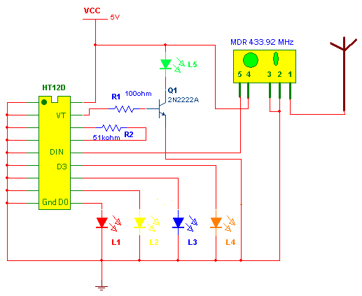
Receiver circuit using IC HT12D is shown in circuit diagram tab 2.


Connections:- All the address lines are connected to ground to set same address. Resistor R2 (51K Ohm) is connected between Oscillator pins. All the data line D0-D3 are connected to different LEDs L1-L4 respectively. LED L5 is connected to VT (valid transmission) pin through transistor Q1 to indicate valid transmission. The Dout pin of 433.92 MHz serial data receiver is connected with Din pin of IC HT12D.

Operation:-

·         When 5V supply is given to circuit all the data lines are low so LEDs will not glow.

·         Whenever you press any switch from Tx address & data are transmitted together

·         The 433.92MHz serial data receiver will demodulate the carrier and gives this address & data to IC HT12D

·         IC HT12D first compares the address three times and if it matches it gives high pulse on VT pin (so LED L5 will blink) and latch the data.

·         Suppose you pressed ‘S4’. So the data transmitted will be 1110 and address will be of course 00000000.

·         HT12D receives the signals compares address thrice, gives high pulse on pin VT and then latch the data. Because data is 1110 LED L1 will not glow and rest all the LEDs will glow.

·         Same way if you press ‘S2’ data will be 1011. So now LED L3 will be off and rests are on.

·         Simply you can see which ever switch is pressed on Tx side that particular data line is low on Rx side. 


Project Source Code


Circuit Diagrams

Transmitter
Rx-2


Filed Under: Electronic Projects
Tagged With: 4 channel, ht 12e, ht12d, remote
 

Questions related to this article?
👉Ask and discuss on EDAboard.com and Electro-Tech-Online.com forums.


Tell Us What You Think!! Cancel reply

You must be logged in to post a comment.

HAVE A QUESTION?

Have a technical question about an article or other engineering questions? Check out our engineering forums EDABoard.com and Electro-Tech-Online.com where you can get those questions asked and answered by your peers!


Featured Tutorials

  • PS2 Keyboard To Store Text In SD Card Using Arduino Circuit Setup On Breadboard
    How To Use PS2 Keyboard To Store Text In SD Card Using Arduino- (Part 42/49)
  • Wireless Path Tracking System Using Mouse, XBee And Arduino Circuit Setup On Breadboard
    How To Make A Wireless Path Tracking System Using Mouse, XBee And Arduino- (Part 43/49)
  • How to Make a Wireless Keyboard Using Xbee with Arduino- (Part 44/49)
  • Making Phone Call From GSM Module Using Arduino Circuit Setup On Breadboard
    How to Make Phonecall From GSM Module Using Arduino- (Part 45/49)
  • How to Make a Call using Keyboard, GSM Module and Arduino
    How To Make A Call Using Keyboard, GSM Module And Arduino- (Part 46/49)
  • Receiving SMS Using GSM Module With Arduino Prototype
    How to Receive SMS Using GSM Module with Arduino- (Part 47/49)

Stay Up To Date

Newsletter Signup

Sign up and receive our weekly newsletter for latest Tech articles, Electronics Projects, Tutorial series and other insightful tech content.

EE Training Center Classrooms

EE Classrooms

Recent Articles

  • Renesas delivers intelligent sensor solutions for IoT applications
  • Microchip Technology releases AVR-IoT Cellular Mini Development Board
  • Qualcomm acquires Cellwize to accelerate 5G adoption and spur infrastructure innovation
  • MediaTek’s chipset offers high-performance option for 5G smartphones
  • Nexperia’s new level translators support legacy and future mobile SIM cards

Most Popular

5G 555 timer circuit 8051 ai Arduino atmega16 automotive avr bluetooth dc motor display Electronic Part Electronic Parts Fujitsu ic infineontechnologies integratedcircuit Intel IoT ir lcd led maximintegratedproducts microchip microchiptechnology Microchip Technology microcontroller microcontrollers mosfet motor powermanagement Raspberry Pi remote renesaselectronics renesaselectronicscorporation Research samsung semiconductor sensor software STMicroelectronics switch Technology vishayintertechnology wireless

RSS EDABOARD.com Discussions

  • about ATmega328 ADC pins
  • Tuning the antenna to be conjugately matched to input impedance of the die
  • Netlist physical name update
  • nt1065_USB3 gnss receiver
  • LLC HB with synchronous rectifiers can be very dodgy?

RSS Electro-Tech-Online.com Discussions

  • undefined reference header file in proteus
  • Capacitor to eliminate speaker hum
  • Decapped Chip On Board
  • Sony KV-A2913E (chassis AE1C) auto shuts off after one minute
  • CRT TV repair
Engineers Garage
  • Analog IC TIps
  • Connector Tips
  • DesignFast
  • EDABoard Forums
  • EE World Online
  • Electro-Tech-Online Forums
  • Microcontroller Tips
  • Power Electronic Tips
  • Sensor Tips
  • Test and Measurement Tips
  • 5G Technology World
  • About Us
  • Contact Us
  • Advertise

Copyright © 2022 WTWH Media LLC. All Rights Reserved. The material on this site may not be reproduced, distributed, transmitted, cached or otherwise used, except with the prior written permission of WTWH Media
Privacy Policy | Advertising | About Us

Search Engineers Garage

  • Projects and Tutorials
    • Electronic Projects
      • 8051
      • Arduino
      • ARM
      • AVR
      • PIC
      • Raspberry pi
      • STM32
    • Tutorials
    • Circuit Design
    • Project Videos
    • Components
  • Articles
    • Tech Articles
    • Insight
    • Invention Stories
    • How to
    • What Is
  • News
    • Electronic Products News
    • DIY Reviews
    • Guest Post
  • Forums
    • EDABoard.com
    • Electro-Tech-Online
    • EG Forum Archive
  • Digi-Key Store
    • Cables, Wires
    • Connectors, Interconnect
    • Discrete
    • Electromechanical
    • Embedded Computers
    • Enclosures, Hardware, Office
    • Integrated Circuits (ICs)
    • Isolators
    • LED/Optoelectronics
    • Passive
    • Power, Circuit Protection
    • Programmers
    • RF, Wireless
    • Semiconductors
    • Sensors, Transducers
    • Test Products
    • Tools
  • EE Resources
    • DesignFast
    • LEAP Awards
    • Oscilloscope Product Finder
    • White Papers
    • Webinars
  • EE Learning Center
    • Design Guides
      • WiFi & the IOT Design Guide
      • Microcontrollers Design Guide
      • State of the Art Inductors Design Guide
  • Women in Engineering