This is very interesting project. It is same as commercial available wireless FM bell but with sweet melody output. It can also be use to operate any AC/DC device from remote and safe place. The range of this remote control is up to 50 meter (basically this depends upon your FM transmitter if you use higher power FM transmitter then range may be increased up to incredible 2 Kilometer or even more then this).
Why FM ?
The advantages of FM over IR are
· The range is increased up to 5 times (from 10 mts. to 50 mts.)
· No need of line of sight means you can operate a device from anywhere in the radius of 50 mts.
· No need to point transmitter at the receiver every time as in case of IR. Just press the button from anywhere even if you are in different room or on the different floor the device will be switched ON or OFF.
· Now the first thing that you need most for this project is the pair of FM transmitter (Tx) and receiver (Rx). There are two options for this. Either you make both transmitter and receiver yourself or you buy it from market. First option is tuff and rather tedious also because making FM Tx & Rx is not simple thing (as far as I am concerned) may be it work or not work properly. So I preferred second option.
· brought standard FM Tx and Rx a pair from market. As a FM Tx I choose FM mike (generally known as cordless mike) and as FM receiver I brought standard FM radio. The cost of both things is less then 150/- Rs.
· Now the first thing you have to do is to find out at which frequency the Tx works. For this you tune FM Radio while keep speaking on FM mike. At one spot you will here the same sound from FM radio that you are speaking. Bingo!!!!!!! that is the frequency of your FM mike. Doing the same experiment I found the frequency of my FM mike is around 108MHz.
Simple FM Bell :-
Now you are halfway through the project. Now you can transmit an audio frequency signal (instead of directly speaking to the mike) from your FM mike. For this you find out the point in FM mike circuit from where the mike signal goes in to FM modulator. It must be some where around condensioner mike. Now remove the mike from the circuit and take out the point for connecting external signal.
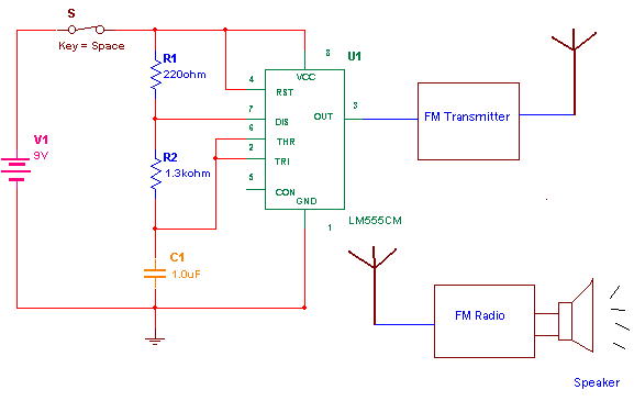
Next is to make audio frequency oscillator. That you can easily make using 555 IC. Build an astable multivibrator of frequency around 500Hz using IC 555. Apply this signal to FM mike. You should here the same 500 Hz sound from FM radio. If not then try again to tune your radio at some point you will here the exact sound. That’s all !!!!!! Your FM remote bell is ready. The circuit is as shown below. When ever you press switch ‘S’ the 500Hz signal is transmitted through FM mike. Same signal will be caught by FM radio and you will here same sound from speaker. You can even adjust the volume of radio to here the sound clearly. Now also you can check out the range even.
Let us do something more interesting with FM Tx & Rx. Let’s extend this project to next step. Now we will use the output signal of FM radio to operate any AC or DC device. So first disconnect the speaker from radio and take out these terminals as output. Again we are going to make FM remote bell but now in a different manner. Again here there are two parts of circuit.
1) Switch for remote bell (Transmitter)
2) Remote bell with melody output (receiver)
Remote Bell output & FM Remote Switch
Switch for remote bell:-
The typical schematic of transmitter is as shown below
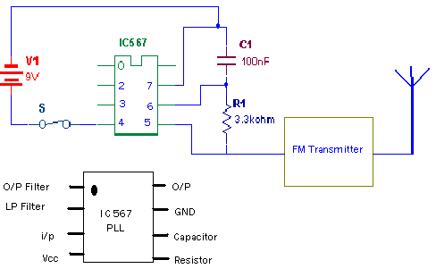
Connection:- Instead of using IC 555 I have used IC 567 which is Phase Lock Loop(PLL) IC. But you can use it as oscillator also by connecting a resistor at a resistor pin (pin no.5) and a capacitor at it’s capacitor pin (pin no.6). The approximate frequency of oscillation is given by equation
F = 1.1*R*C
The output signal is given to FM Tx. (Note:- when you are using IC 567 as oscillator the o/p is taken from pin no.5 instead of the o/p pin no.8). Now when ever press switch s the the frequency signal of 2.75 KHz is transmitted through FM Tx.
Remote bell with melody output:-
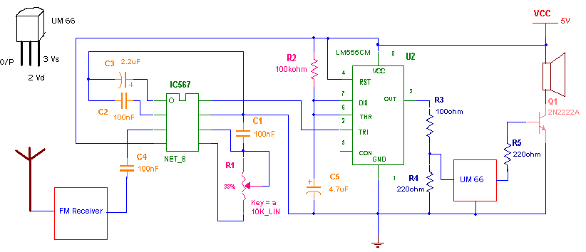
Receiver circuit is shown in Circuit Diagram 1 tab.
Connection:- The main components of the circuit are IC 567(PLL), IC 555(monostable multivibrator) and UM 66(melody generator). The Signal o/p taken from FM radio is coupled to i/p of IC 567 through 100nf capacitor. The o/p of PLL is given to trigger i/p(pin no.2) IC 555. It is connected in monostable multivibrator mode. This o/p is given to i/p of (pin no 3 Vs) melody generator IC UM 66 through voltage divider form by resistors R3 and R4. The o/p of chip UM66 will drive the speaker through transistor Q1 of type 2N2222A.
Tunning of receiver:-
Here again I have used IC 567 but here it is used as a phase lock loop. Means it’s output will go low at specific frequency determine by RC components. So you have to tune it with the transmitter signal frequency using pot R1. What you do is in transmitter just keep switch ‘S’ pressed. That means it will continuously generate signal of 2.75 KHz. Then start rotating knob of pot R1 at one point (near about 3.3K) the o/p of PLL will goes low (this you can see bu connecting LED between +Vcc and O/p pin no. 8 of IC 567 connect anode with +Vcc and cathode with pin no.8. So whenever output goes low LED will glow). Now check 2 to 3 times by pressing switch ‘S’ whether LED glows or not ? If it glows every time that means there is perfect tuning between Tx and Rx.
Operation:-
· When you press switch S from the transmitter 2.75KHz signal is generated and it will be modulated by FM Tx.
· This FM modulated signal is demodulated by FM radio and given to PLL IC 567
· This IC detects 2.75 KHz signal and gives low o/p
· This low o/p triggers IC 555 and it will generate high pulse of 4 sec.
· Because this high pulse is given to melody generator IC UM 66 you will here sweet sound for 4 sec.
· The process repeats every time when you press switch S
So actually transmitter works as remote (and also wireless) switch for bell. You can mount both the circuits in a radius of 50 mts. No need of any kind of wire connection between switch and a bell.
FM Remote Switch:-
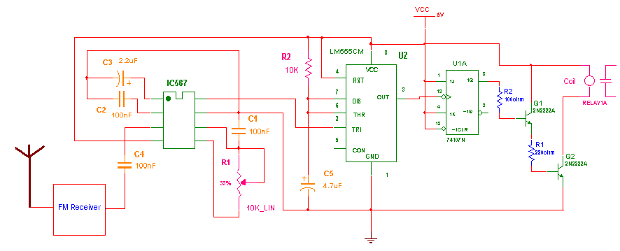
With slight modification in above circuit one can operate any home appliance from a remote place. The arrangement will be as shown Circuit Diagram Tab2.
in above circuit when IC555 receives trig i/p it will produce a pulse o/p of around 0.5 sec. This pulse is given as clock i/p to dual JK flip flop chip 74LS107. It will give toggle output (Means if it’s high then on receiving clock pulse it will be low and vice versa). This o/p turns relay ON/OFF through darlignton connection of two transistors Q1 & Q2. Relay is connected with any home appliance to switch it ON or OFF.
Project Source Code
Circuit Diagrams
Filed Under: Electronic Projects
Log in to leave a comment:
Lost your password?
Don't have an account? Register here